Dodge Neon / Neon SRT-4. Manual - part 320


  Index      Dodge     Dodge Neon / Neon SRT-4 - service repair manual 2005 year


Search            


Content   ..  318  319  320  321   ..


Dodge Neon / Neon SRT-4. Manual - part 320


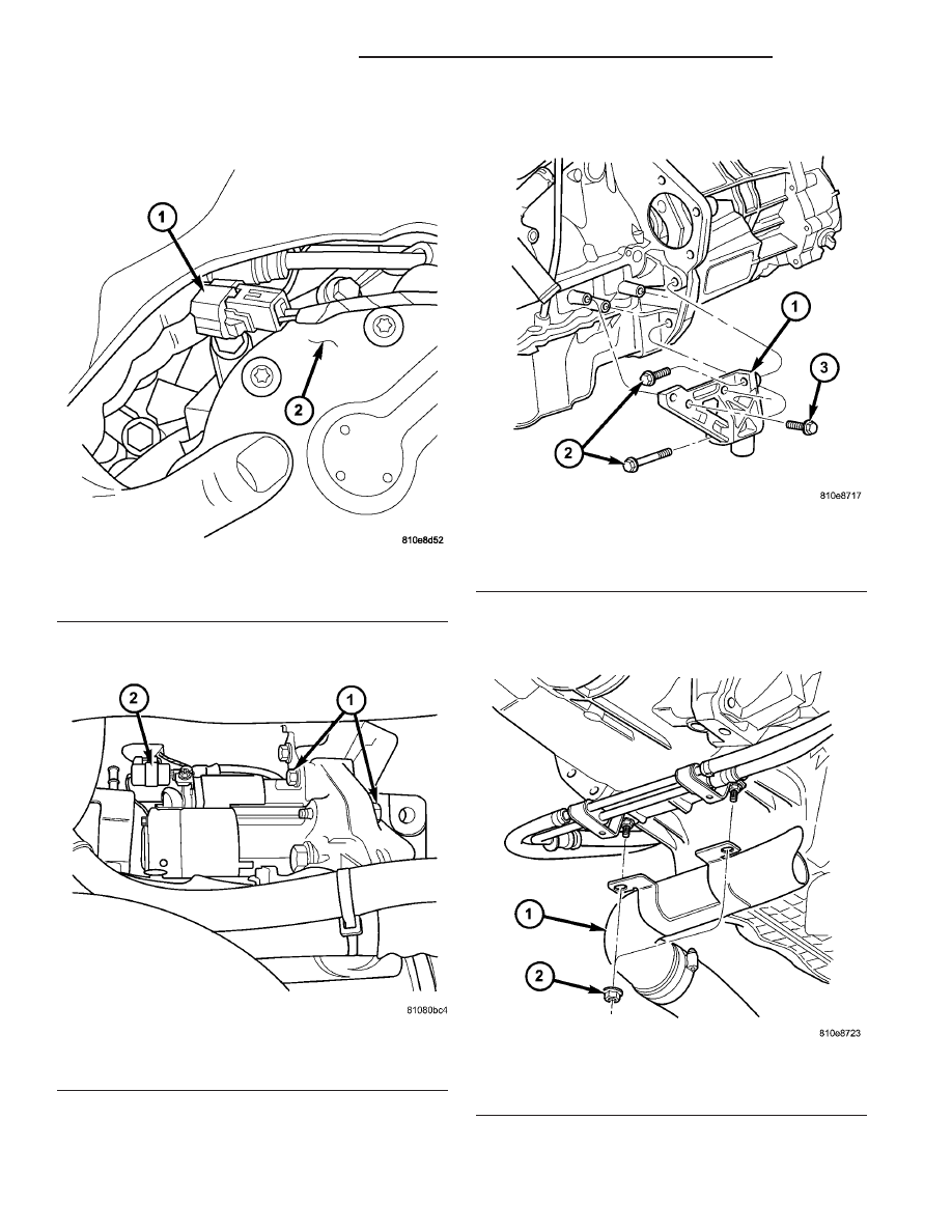
(17) Disconnect back-up lamp switch connector

(Fig. 14).

(18) Remove three (3) starter motor-to-transaxle

case bolts (Fig. 15).

(19) Remove front lateral bending brace (Fig. 16).

(20) Disconnect turbocharger pipe and power steer-

ing lines from structural collar (Fig. 17) (Fig. 18).

Fig. 14 Back-up Lamp Switch Connector

1 - CONNECTOR
2 - END COVER

Fig. 15 Starter Motor-to-Transaxle Case Bolts

1 - MOUNTING BOLTS (3)
2 - CONNECTOR

Fig. 16 Lateral Bending Brace

1 - LATERAL BENDING BRACE
2 - BOLT (1 LONG/1 SHORT)
3 - BOLT (2)

Fig. 17 Charge Air Cooler Hose/Fasteners

1 - CAC HOSE ASSY
2 - NUT (2)

21 - 64

T850 MANUAL TRANSAXLE

PL/SRT-4

T850 MANUAL TRANSAXLE (Continued)

(21) Remove structural collar (Fig. 19).

(22) Remove

four

(4)

modular

clutch-to-engine

drive plate bolts (Fig. 20). While removing bolts, one
tight-tolerance (slotted) hole will be encountered.

When this bolt is removed, mark driveplate and mod-
ular clutch assembly at this location, and be sure to
align marks upon reassembly.

(23) Install and secure transmission jack.
(24) Remove left mount through-bolt.
(25) Lower engine/transaxle assembly enough to

gain access to left mount and bellhousing bolts.

(26) Remove left mount-to-transaxle bolts. Remove

mount (Fig. 21).

Fig. 18 Structural Collar/Power Steering Hose

Fasteners

1 - POWER STEERING HOSE ASSY
2 - BOLT/STUD (2)

Fig. 19 Structural Collar Removal/Installation

1 - STRUCTURAL COLLAR
2 - BOLT

Fig. 20 Modular Clutch-to-Driveplate Bolts

1 - DRIVEPLATE
2 - MODULAR CLUTCH ASSEMBLY
3 - TIGHT TOLERANCE HOLE
4 - BOLT (4)

Fig. 21 Transaxle Upper Mount and Fasteners

1 - MOUNT/BRACKET
2 - BOLT (3)

PL/SRT-4

T850 MANUAL TRANSAXLE

21 - 65

T850 MANUAL TRANSAXLE (Continued)

(27) Install screw jack and wood block to support

engine after transmission removal.

(28) Remove

transmission

bellhousing-to-block

bolts and remove transmission and modular clutch
assembly.

(29) If replacing transmission, transfer impact

blocker, back-up lamp switch, vehicle speed sensor
and gearshift cable bracket.

DISASSEMBLY

(1) Remove clutch release lever and bearing (Fig.

22). Inspect release lever pivot balls and replace if
necessary (Fig. 23). Use slide hammer C-3752 and
remover/installer 6891 (Fig. 24) if pivot ball replace-
ment is necessary.

(2) Remove input shaft bearing retainer (Fig. 25).

Fig. 22 Release Bearing and Lever

1 - RELEASE LEVER
2 - RELEASE BEARING

Fig. 23 Pivot Ball Orientation

1 - PIVOT BALL (1)

Fig. 24 Pivot Ball Removal/Installation

1 - C-3752 SLIDE HAMMER
2 - REMOVER/INSTALLER 6891
3 - PIVOT BALL

21 - 66

T850 MANUAL TRANSAXLE

PL/SRT-4

T850 MANUAL TRANSAXLE (Continued)

NOTE: Place transaxle in neutral before shift cover
removal. It may be necessary to remove selector
lever from cover to gain access to and remove one
fastener.

(3) Remove shift cover-to-case bolts and remove

shift cover assembly (Fig. 26).

(4) Using a suitable screwdriver, remove and dis-

card extension housing axle oil seal (Fig. 27).

(5) Remove extension housing-to-case and differen-

tial cover bolts (Fig. 28).

(6) Place transaxle with bellhousing surface down.
(7) Remove backup lamp switch (Fig. 29).

Fig. 25 Input Bearing Retainer

1 - INPUT BEARING RETAINER

Fig. 26 Shift Cover Removal/Installation

1 - SHIFT COVER ASSEMBLY

Fig. 27 Extension Housing Seal

1 - SCREWDRIVER
2 - EXTENSION HOUSING
3 - SEAL - DISCARD UPON REMOVAL

Fig. 28 Extension Housing-to-Case Bolts

1 - EXTENSION HOUSING

PL/SRT-4

T850 MANUAL TRANSAXLE

21 - 67

T850 MANUAL TRANSAXLE (Continued)


Content   ..  318  319  320  321   ..