Dodge Neon / Neon SRT-4. Manual - part 319
5TH GEAR
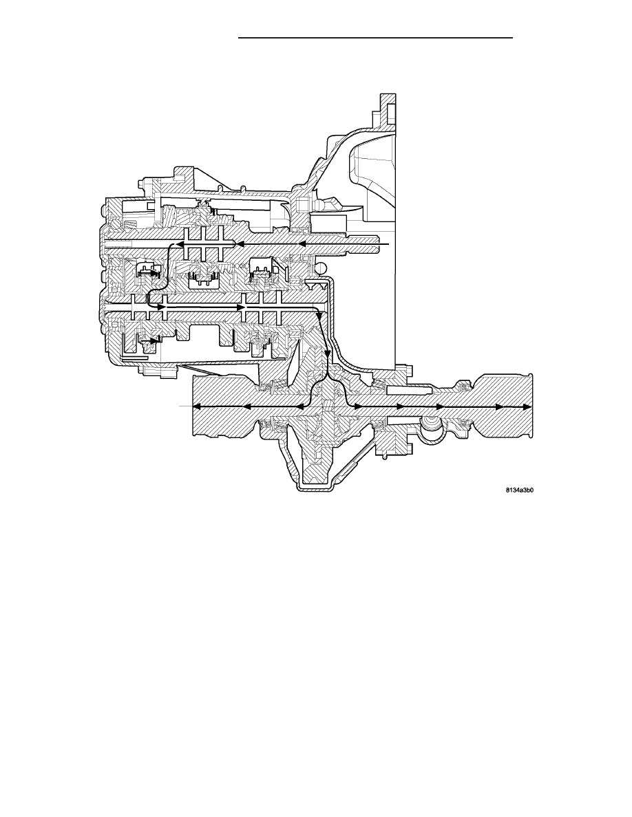
Engine power is transmitted to the input shaft via
the clutch assembly and the input shaft turns. The
input shaft fifth gear is pressed on to the input shaft,
and is in constant mesh with the intermediate shaft
fifth speed gear. Because of this constant mesh, the
intermediate shaft fifth speed gear freewheels until
fifth gear is selected. As the gearshift lever is moved
to the fifth gear position, the 5-R fork moves the 5-R
synchronizer sleeve towards the intermediate shaft
fifth speed gear. The synchronizer sleeve engages the
fifth gear clutch teeth, fixing the gear to the input
shaft, and allowing power to transmit through the
intermediate shaft to the differential (Fig. 8).
Fig. 8 5th Gear Operation
21 - 60
T850 MANUAL TRANSAXLE
PL/SRT-4
T850 MANUAL TRANSAXLE (Continued)