Dodge Neon / Neon SRT-4. Manual - part 312


  Index      Dodge     Dodge Neon / Neon SRT-4 - service repair manual 2005 year


Search            


Content   ..  310  311  312  313   ..


Dodge Neon / Neon SRT-4. Manual - part 312


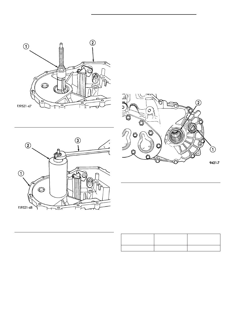
(2) Install Miller tool #L-4518 into the differential

bearing cup (Fig. 87).

(3) Install the tool cup over the tool (Fig. 88).

(4) Tighten the tool until the race is removed from

the case.

INSTALLATION

(1) Position the bearing cup into the case.
(2) Install

the

bearing

cup

onto

Miller

tool

#L-4520.

(3) Using Miller tool #L-4520 and C-4171 driver,

install differential bearing cup into the transaxle
case.

FLUID

STANDARD PROCEDURE - FLUID DRAIN AND
FILL

NOTE: The fluid required in this transaxle is Mopar

T

ATF+4 (Automatic Transmission Fluid—Type 9602).

All T350 transaxles are equipped with a fill plug.

The fill plug is located on the left side of the trans-
axle differential area (Fig. 89). The fluid level should
be within 3/16 inch from the bottom of the transaxle
fill hole (vehicle must be level when checking).

All T350 transaxles are equipped with a drain

plug. The drain plug is located on the lower right
side of the transaxle differential housing (Fig. 90).
Tighten drain plug to 28 N·m (250 in. lbs.)

Fill transaxle to capacity. Refer to following chart.

Wipe the outside of the transaxle if any lubricant
spills.

NV T350 MANUAL TRANSAXLE FLUID FILL

TRANSAXLE

METRIC

MEASURE

U.S. MEASURE

NV T350

2.4-2.7 Liters

2.5-2.8 Quarts

Fig. 87 Tool Installed in Bearing

1 - SPECIAL TOOL L-4518
2 - GEAR CASE

Fig. 88 Tool Cup Installed

1 - GEAR CASE
2 - SPECIAL TOOL L-4518
3 - WRENCH

Fig. 89 Fill Plug Location

1 - RUBBER FILL PLUG
2 - LEFT DRIVESHAFT SEAL

21 - 32

T350 MANUAL TRANSAXLE

PL/SRT-4

DIFFERENTIAL BEARING CUPS (Continued)

GEAR SHIFT CABLE

REMOVAL

NOTE: The crossover and selector cables are man-
ufactured as a cable “assembly” and cannot be ser-
viced individually.

(1) Raise hood and disconnect battery negative

cable.

(2) Disengage gearshift boot from center console.
(3) Push down on knob and rotate clockwise to

remove gearshift boot/knob assy (Fig. 91).

(4) Remove the center console assembly as shown

in (Fig. 92).

(5) Remove crossover cable retaining clip and dis-

connect from shift lever (Fig. 93).

Fig. 90 Drain Plug Location

1 - DRAIN PLUG

Fig. 91 Gearshift Knob/Boot Removal

1 - GEARSHIFT KNOB

Fig. 92 Center Console

1 - CONSOLE
2 - SCREW (4)
3 - SCREW (2)

Fig. 93 Crossover Cable at Shifter Assembly

1 - GROMMET PLATE NUT
2 - SHIFTER
3 - CROSSOVER CABLE
4 - CLIP

PL/SRT-4

T350 MANUAL TRANSAXLE

21 - 33

FLUID (Continued)

(6) Remove selector cable retaining clip and dis-

connect from shift lever (Fig. 94).

(7) Remove

three

grommet

plate-to-floor

pan

attaching nuts (Fig. 93).

(8) Remove air cleaner/throttle body assy. (Fig.

95)as follows:

(a) Disconnect proportional purge solenoid (PPS)

and crankcase vent hose from throttle body.

(b) Disconnect

the

Throttle

Position

Sensor

(TPS) and Idle Air Control (IAC) connectors.

(c) Disconnect throttle body air duct from intake

manifold.

(d) Remove mounting bolt and nut (Fig. 95) and

partially remove air cleaner assembly.

(e) Disconnect accelerator and speed control (if

equipped) cables after the assy. is removed from
position. Remove air cleaner assembly from vehi-
cle.
(9) Disconnect cables from the shift levers at the

transaxle (Fig. 96).

CAUTION: Pry up with equal force on both sides of
shifter cable isolator bushings to avoid damaging
cable isolator bushings.

Remove cable retaining clips and remove cables

from bracket (Fig. 96).

(10) Raise vehicle on hoist.
(11) Remove converter heat shield (Fig. 97).
(12) Remove remaining grommet plate-to-floor pan

screw (Fig. 98).

(13) Remove cable assembly from vehicle.

INSTALLATION

NOTE: The crossover and selector cables are man-
ufactured as a cable “assembly” and cannot be ser-
viced individually.

CAUTION: Gearshift cable bushings must not be
lubricated or the bushings will swell and split.

(1) Raise vehicle on hoist.

Fig. 94 Selector Cable at Shifter Assembly

1 - SHIFTER
2 - CLIP
3 - SELECTOR CABLE

Fig. 95 Air Cleaner Assembly Removal/Installation

1 - AIR CLEANER ASSY.
2 - THROTTLE BODY DUCT

Fig. 96 Shift Cables at Transaxle

1 - SHIFT CABLES
2 - CLIPS
3 - BRACKET

21 - 34

T350 MANUAL TRANSAXLE

PL/SRT-4

GEAR SHIFT CABLE (Continued)

(2) Install cable assembly through floor pan open-

ing and secure to floor pan with grommet plate and
one screw (Fig. 98). Make sure the three grommet
plate studs protrude through cable assembly and
floor pan and tighten screw to 7 N·m (60 in. lbs.).

(3) Route transaxle end of cable assembly into

engine compartment and over transaxle assembly.

(4) Install converter heat shield (Fig. 97).
(5) Lower vehicle.
(6) Install gearshift cables to mounting bracket

and fasten with NEW clips (Fig. 96). Make sure clips
are installed flush to bracket.

(7) Connect gearshift selector and crossover cable

to shift levers at transaxle (Fig. 96).

(8) Install and tighten the three grommet plate-to-

floor pan nuts to 6 N·m (50 in. lbs.) torque.

(9) Install selector cable to shifter lever and secure

cable to shifter bracket. Install clip (Fig. 94).

(10) Install crossover cable to shifter lever and

secure cable to shifter bracket. Install clip (Fig. 93).

NOTE: Only the crossover cable is adjustable. The
selector cable does not have any adjustment capa-
bilities.

(11) Adjust crossover cable as follows:

(a) Loosen adjusting screw on crossover cable at

shifter (Fig. 99).

(b) The

gearshift

mechanism

and

transaxle

crossover lever are spring-loaded and self-center-
ing. Alignment pins used in the past are not
required anymore. Allow gearshift mechanism and
transaxle crossover lever to relax in their neutral
positions. To ensure the gearshift lever is in the
proper position, place the shifter in 3rd or 4th gear
if necessary. Torque adjustment screw to 8 N·m (70
in. lbs.). Care must be taken to avoid moving the
shift mechanism off-center during screw tighten-
ing.

(c) Perform functional check by shifting trans-

axle into all gears.

(12) Install center console assembly (Fig. 92). Ver-

ify that boot is not pinched at console opening before
tightening.

(13) Install knob/boot assembly to shifter lever,

align knob to three o’clock position, push knob down
to engage spring and rotate counter clockwise to
secure (Fig. 91).

(14) Locate boot to console at forward tab and

secure with retaining tabs.

Fig. 97 Converter Heat Shield Removal/Installation

1 - CONVERTER HEAT SHIELD

Fig. 98 Shift Cable Assembly at Floor Pan

1 - CABLE ASSEMBLY
2 - GROMMET PLATE

Fig. 99 Crossover Cable Adjustment Screw

1 - CROSSOVER ADJUSTMENT SCREW

PL/SRT-4

T350 MANUAL TRANSAXLE

21 - 35

GEAR SHIFT CABLE (Continued)


Content   ..  310  311  312  313   ..