Dodge Neon / Neon SRT-4. Manual - part 297


  Index      Dodge     Dodge Neon / Neon SRT-4 - service repair manual 2005 year


Search            


Content   ..  295  296  297  298   ..


Dodge Neon / Neon SRT-4. Manual - part 297


INSPECTION PROCEDURE

(1) Place the steering wheel in the STRAIGHT-

AHEAD position. Using a steering wheel holding
clamp, lock the steering wheel in place to keep it
from rotating. This keeps the clockspring in the
proper orientation.

(2) Inside the passenger compartment, remove the

steering column coupling retainer pin, back off the
pinch bolt nut, and remove the steering column cou-
pling pinch bolt (Fig. 23) (the pinch bolt nut is caged
to the coupling and is not removable). Separate the
upper and lower steering column couplings.

(3) Remove the silencer seal enclosing the steering

column coupling (Fig. 24).

(4) Inspect steering column lower coupling in the

following areas for signs of damage:

• Inspect the lower coupling flex joint for binding.

• Inspect the sealing collar on the lower coupling

(Fig. 25) to ensure the it is not cracked, broken, or
otherwise damaged requiring coupling replacement.

• Inspect the corrugated section (Fig. 25) of the

lower coupling for the following conditions or any
other visible signs of damage.

− Uneven spacing between the corrugations on

the coupling.

− Dings or dents in the corrugations of the cou-

pling or anywhere else on the coupling wall.

− A bend in the corrugated section of the cou-

pling.
If any of the preceding conditions exist, the steer-

ing column lower coupling must be replaced.

Inspect the steering column upper coupling for

damage or binding. If the upper coupling needs to be
replaced, the steering column must be replaced.

NOTE: Verify that grease is present on the lip of the
dash-to-coupling seal where it contacts the lower
coupling’s plastic collar.

(5) If the lower coupling does not require replace-

ment, install the dash panel-to-steering column cou-
pling silencer seal (Fig. 24) back on the vehicle.

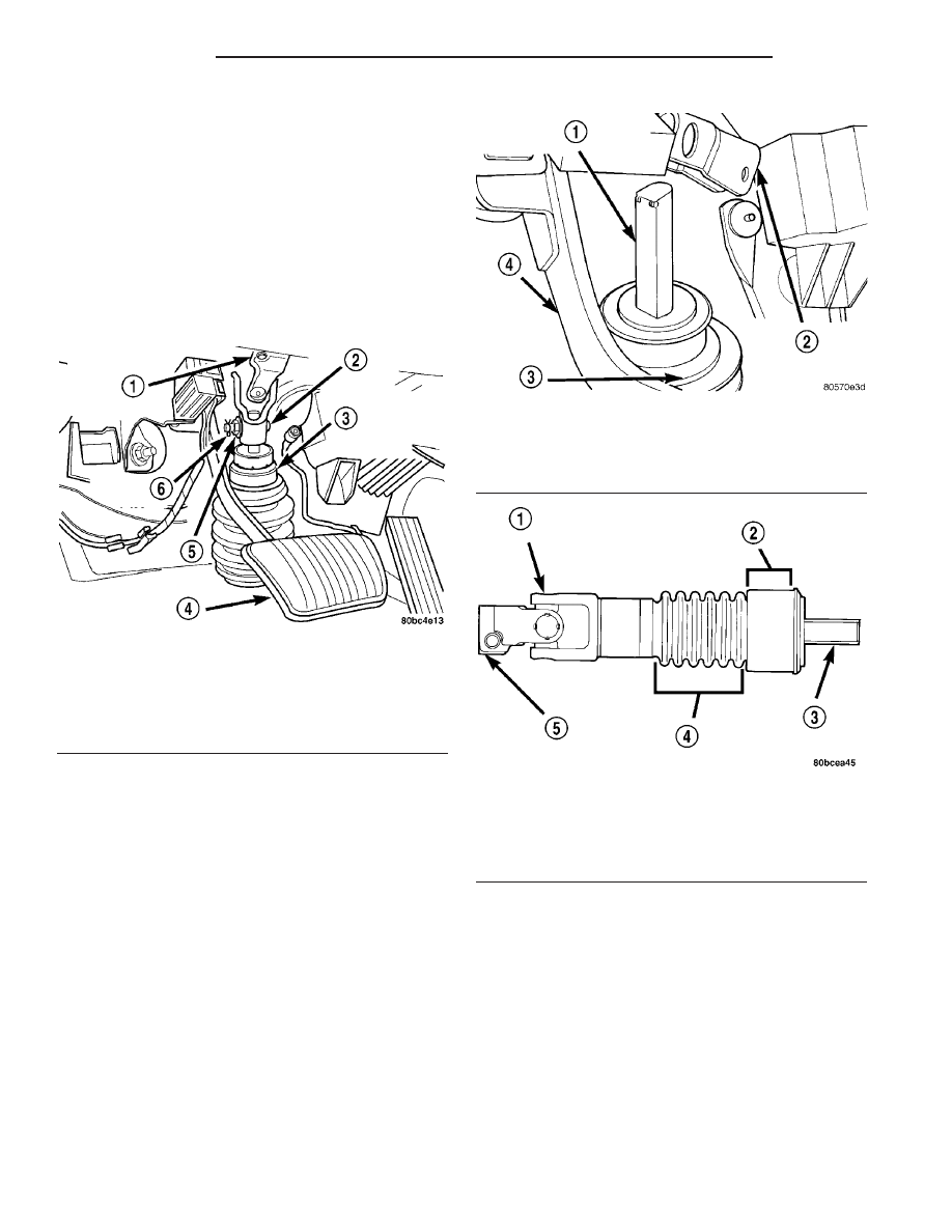
Fig. 23 Steering Column Couplings

1 - STEERING COLUMN UPPER COUPLING
2 - PINCH BOLT
3 - STEERING COLUMN LOWER COUPLING
4 - BRAKE PEDAL
5 - NUT
6 - RETAINER PIN

Fig. 24 Steering Column Coupling Seal

1 - LOWER STEERING COLUMN COUPLER
2 - UPPER STEERING COLUMN SHAFT COUPLER
3 - SILENCER SEAL
4 - BRAKE PEDAL

Fig. 25 Lower Coupling Inspection

1 - FLEX JOINT
2 - SEAL COLLAR SEALING SURFACE
3 - TO STEERING COLUMN
4 - CORRUGAGATED TUBE SECTION
5 - TO STEERING GEAR

19 - 20

COLUMN

PL/SRT-4

STEERING COUPLING - LOWER (Continued)

NOTE: Do not tighten the coupling pinch bolt any-
time the vehicle is not at curb riding height. It may
cause unwanted conditions within the steering col-
umn if the vehicle is suspended in any manner
when the pinch bolt is tightened.

(6) Ensure front wheels of vehicle are posi-

tioned STRAIGHT-AHEAD and the steering col-
umn is in the full tilt-up position with the tilt
lever secured.
Align and attach the steering column
upper coupling to the lower coupling. Install the cou-
pling pinch bolt (Fig. 23). Tighten the pinch bolt nut
to a torque of 28 N·m (250 in. lbs.).

(7) Install the coupling pinch bolt retainer pin.
(8) Remove the steering wheel holding clamp.

REMOVAL - STEERING COLUMN LOWER
COUPLING

NOTE: Before proceeding with this procedure,
(Refer to 19 - STEERING/COLUMN - WARNING).

(1) Place the steering wheel in the STRAIGHT-

AHEAD position. Using a steering wheel holder, lock
the steering wheel in place to keep it from rotating
(Fig. 26). This keeps the clockspring in the proper
orientation.

(2) Inside the passenger compartment, remove the

steering column coupling retainer pin, back off the
pinch bolt nut, and remove the steering column cou-
pling pinch bolt (Fig. 27) (the pinch bolt nut is caged
to the coupling and is not removable). Separate the
upper and lower steering column couplings.

(3) Raise the vehicle. (Refer to LUBRICATION &

MAINTENANCE/HOISTING - STANDARD PROCE-
DURE).

(4) Release the locking tab on the wiring harness

connector for the power steering fluid pressure
switch before connector removal. Remove the wiring
harness connector from the power steering fluid pres-
sure switch (Fig. 28).

(5) Remove the drive-belt splash shield fasteners.

Remove the shield.

(6) Remove the pencil strut from the right front

corner of the crossmember and body of the vehicle
(Fig. 29). Remove the washer behind the strut from
the torque strut bolt.

Fig. 26 Steering Wheel Holder (Typical)

1 - STEERING WHEEL
2 - STEERING WHEEL HOLDER
3 - DRIVERS SEAT

Fig. 27 Steering Column Couplings

1 - STEERING COLUMN UPPER COUPLING
2 - PINCH BOLT
3 - STEERING COLUMN LOWER COUPLING
4 - BRAKE PEDAL
5 - NUT
6 - RETAINER PIN

Fig. 28 Power Steering Fluid Pressure Switch

1 - WIRING HARNESS CONNECTOR
2 - POWER STEERING GEAR
3 - POWER STEERING FLUID PRESSURE SWITCH
4 - REAR OF FRONT SUSPENSION CROSSMEMBER

PL/SRT-4

COLUMN

19 - 21

STEERING COUPLING - LOWER (Continued)

(7) Remove the bolts mounting the engine torque

strut in place (Fig. 29), then remove the engine
torque strut from the vehicle.

NOTE: Before removing the front suspension cross-
member from the vehicle, the location of the cross-
member must be scribed on the body of the vehicle
(Fig. 9). Do this so that the crossmember can be
relocated upon reinstallation against the body of
vehicle in the same location as before removal. If
the front suspension crossmember is not rein-
stalled in exactly the same location as before
removal, the preset front wheel alignment settings
(caster and camber) will be lost.

(8) Using an awl, scribe a line (Fig. 30) marking

the location of where the front suspension crossmem-
ber is mounted against the body of the vehicle.

(9) Position a transmission jack under the center

of the front suspension crossmember and raise it to
support the bottom of the crossmember.

(10) Loosen and completely remove the two front

bolts (one right and one left) attaching the front sus-
pension crossmember to the frame rails of vehicle.
The right side bolt can be viewed in the mounting
bolt figure (Fig. 31). The left side bolt is located in
the same location on the other side of the vehicle.

(11) Loosen the two rear bolts (one right and one

left) attaching the front suspension crossmember and
lower control arms to the body of the vehicle until
they release from the threaded tapping plates in the
body of the vehicle. Do not completely remove the
rear bolts because they are designed to disengage
from the body threads yet stay within the lower con-
trol arm rear isolator bushing. This allows the lower
control arm to stay in place on the crossmember. The

right side bolt can be viewed in the mounting bolt
figure (Fig. 31). The left side bolt is located in the
same location on the other side of the vehicle.

CAUTION: Lower the steering gear slowly, paying
special attention to the power steering fluid hoses
coming down from the power steering pump. Do
not strain or over extend the hoses coming to the
gear. Damage to the hoses or connecting hardware
could occur.

(12) Lower

the

front

suspension

crossmember

using the transmission jack enough to allow suffi-
cient access to the steering column lower coupling
(Fig. 32). When lowering front suspension crossmem-

Fig. 29 Strut Mounting

1 - NUT
2 - PENCIL STRUT
3 - NUT
4 - FLAT WASHER
5 - LOWER TORQUE STRUT

Fig. 30 Marking Crossmember Location

1 - SCRIBED LINE
2 - FRONT SUSPENSION CROSSMEMBER
3 - AWL
4 - BODY

Fig. 31 Mounting Bolts

1 - FRONT SUSPENSION CROSSMEMBER MOUNTING BOLTS
2 - ENGINE TORQUE ISOLATOR STRUT MOUNTING BOLT
3 - FRONT SUSPENSION CROSSMEMBER

19 - 22

COLUMN

PL/SRT-4

STEERING COUPLING - LOWER (Continued)

ber, do not let crossmember hang from lower control
arms or power steering hoses. The weight should be
supported by the transmission jack.

(13) Remove the roll pin securing the steering col-

umn lower coupling to the power steering gear pinion
shaft using a roll pin punch (Fig. 33). Push the steer-
ing column lower coupling up and off of the power
steering gear pinion shaft.

INSTALLATION - STEERING COLUMN LOWER
COUPLING

NOTE: Before proceeding with this procedure,
(Refer to 19 - STEERING/COLUMN - WARNING).

(1) Push the column end of the steering column

lower coupling partway up through its hole in the
dash panel, then match the flat on the inside of the
steering column lower coupling to the flat on the
power steering gear pinion shaft and slide the cou-
pling onto the top of the pinion shaft. Align the roll
pin hole in the coupling with the groove in the pinion
shaft and install the roll pin through the coupling
until it is centered (Fig. 33).

(2) Center the power steering gear rack in its

travel.

(3) Using the transmission jack, raise the front

suspension crossmember and power steering gear
until the crossmember contacts its mounting spot
against the body and frame rails of the vehicle. As
the crossmember is raised, carefully guide the steer-
ing column lower coupling up through its hole in the
dash panel.

(4) Start the two rear crossmember mounting bolts

into the tapping plates mounted in the body. The
right side bolt can be viewed in the mounting bolt
figure (Fig. 31). The left side bolt is located in the
same location on the other side of the vehicle. Next,
install the two front mounting bolts attaching front
suspension crossmember to frame rails of vehicle.
Lightly tighten all four mounting bolts to a approxi-
mately 2 N·m (20 in. lbs.) to hold the front suspen-
sion crossmember in position.

NOTE:

When

reinstalling

the

front

suspension

crossmember back in the vehicle, it is very impor-
tant that the crossmember be attached to the body
in exactly the same spot as when it was removed.
Otherwise, the vehicle’s wheel alignment settings
(caster and camber) will be lost.

(5) Using a soft face hammer, tap the front suspen-

sion crossmember back-and-forth or side-to-side until
it is aligned with the previously scribed positioning
marks on the body of the vehicle (Fig. 30). Once the
front suspension crossmember is correctly positioned,
tighten the rear two crossmember mounting bolts to
a torque of 203 N·m (150 ft. lbs.), then tighten the
front two crossmember mounting bolts to a torque of
142 N·m (105 ft. lbs.).

(6) Install the engine torque strut and mounting

bolts (Fig. 29). To properly align and tighten the
torque

strut,

(Refer

to

9

-

ENGINE/ENGINE

MOUNTING/TORQUE STRUT - ADJUSTMENTS).

(7) Install the washer on the end of the stud

extending from the torque strut bolt (Fig. 29).

(8) Install the pencil strut to the right front corner

of the crossmember and body of the vehicle (Fig. 29).
Tighten the pencil strut nuts to a torque of 58 N·m
(43 ft. lbs.).

(9) Install the drive-belt splash shield and fasten-

ers.

Fig. 32 Crossmember Lowered

1 - STEERING COLUMN LOWER COUPLING
2 - POWER STEERING GEAR
3 - FRONT SUSPENSION CROSSMEMBER
4 - TRANSMISSION JACK

Fig. 33 Coupling Roll Pin

1 - STEERING COLUMN LOWER COUPLING
2 - POWER STEERING GEAR PINION SHAFT
3 - ROLL PIN
4 - ROLL PIN PUNCH

PL/SRT-4

COLUMN

19 - 23

STEERING COUPLING - LOWER (Continued)


Content   ..  295  296  297  298   ..