Dodge Neon / Neon SRT-4. Manual - part 298
(10) Reconnect the wiring harness connector to the
power steering fluid pressure switch (Fig. 28). Be
sure the locking tab on the wiring harness connector
is securely latched.
(11) Lower the vehicle to ground level.
(12) Install the dash-to-lower coupling seal in
place over the lower coupling’s plastic collar.
NOTE: Verify that grease is present on the lip of the
dash-to-coupling seal where it contacts the cou-
pling’s plastic collar.
(13) Inside the passenger compartment, position
the steering column in the full tilt-up position
and secure the tilt lever, then reconnect the steer-
ing column lower coupling to the steering column
upper coupling (Fig. 27). Install the coupling pinch
bolt an tighten the pinch bolt nut to a torque of 28
N·m (250 in. lbs.). Install the pinch bolt retainer pin.
(14) Remove the steering wheel holder.
(15) While looking under the instrument panel at
the lower coupling, rotate the steering wheel back-
and-forth to verify that the lower coupling does not
squeak against the dash-to-coupling seal.
STEERING WHEEL
REMOVAL
WARNING: DISCONNECT AND ISOLATE THE BAT-
TERY
NEGATIVE
(GROUND)
CABLE
BEFORE
BEGINNING ANY AIRBAG SYSTEM COMPONENT
REMOVAL OR INSTALLATION PROCEDURE. THIS
WILL DISABLE THE AIRBAG SYSTEM. FAILURE TO
DISCONNECT BATTERY COULD RESULT IN ACCI-
DENTAL AIRBAG DEPLOYMENT AND POSSIBLE
PERSONAL INJURY.
WARNING: ALLOW SYSTEM CAPACITOR TO DIS-
CHARGE FOR 2 MINUTES BEFORE REMOVING ANY
AIRBAG COMPONENTS.
(1) Adjust the steering wheel so that the tires are
in the STRAIGHT-AHEAD position.
NOTE: The steering column on vehicles with an
automatic transmission may not be equipped with
an internal locking shaft that allows the ignition key
cylinder to be locked with the key. Alternative meth-
ods of locking the steering wheel for service will
have to be used.
(2) Disconnect and isolate the battery negative
cable.
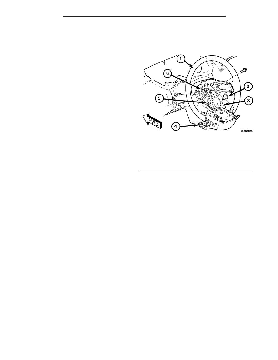
(3) Remove the two mounting screws, one on each
side of steering wheel, attaching the driver airbag to
the steering wheel (Fig. 34).
(4) Lay the driver airbag back away from the cen-
ter of the steering wheel (Fig. 34). Disconnect the air-
bag squib and horn switch wiring connectors from
the rear of the airbag. Remove the driver airbag from
the steering wheel.
(5) If equipped with speed control, disconnect the
wiring connector from the speed control switch (Fig.
34).
(6) Holding the steering wheel firmly in place,
remove the steering wheel retaining screw from the
steering column shaft (Fig. 35).
CAUTION: When installing a wheel puller on the
steering wheel, be sure the puller bolts are fully
seated in the threaded holes on the steering wheel.
If the bolts are not fully seated in the threaded
holes, the threads may be stripped out of the steer-
ing wheel when attempting to remove the steering
wheel. Also, thread the retaining nut back on the
end of the shaft until it is flush with the shaft end to
avoid damage to the shaft threads by the wheel
puller.
(7) Install a steering wheel puller on the steering
wheel.
CAUTION: Do not bump or hammer on steering
wheel or steering column shaft when removing
steering wheel from steering column.
Fig. 34 Airbag Mounting And Wiring Connections
1 - STEERING WHEEL
2 - SPEED CONTROL SWITCH (IF EQUIPPED)
3 - AIRBAG SQUIB CONNECTOR
4 - DRIVER AIRBAG
5 - HORN SWITCH CONNECTOR
6 - SPEED CONTROL SWITCH CONNECTOR (IF EQUIPPED)
19 - 24
COLUMN
PL/SRT-4
STEERING COUPLING - LOWER (Continued)