Dodge Neon / Neon SRT-4. Manual - part 294
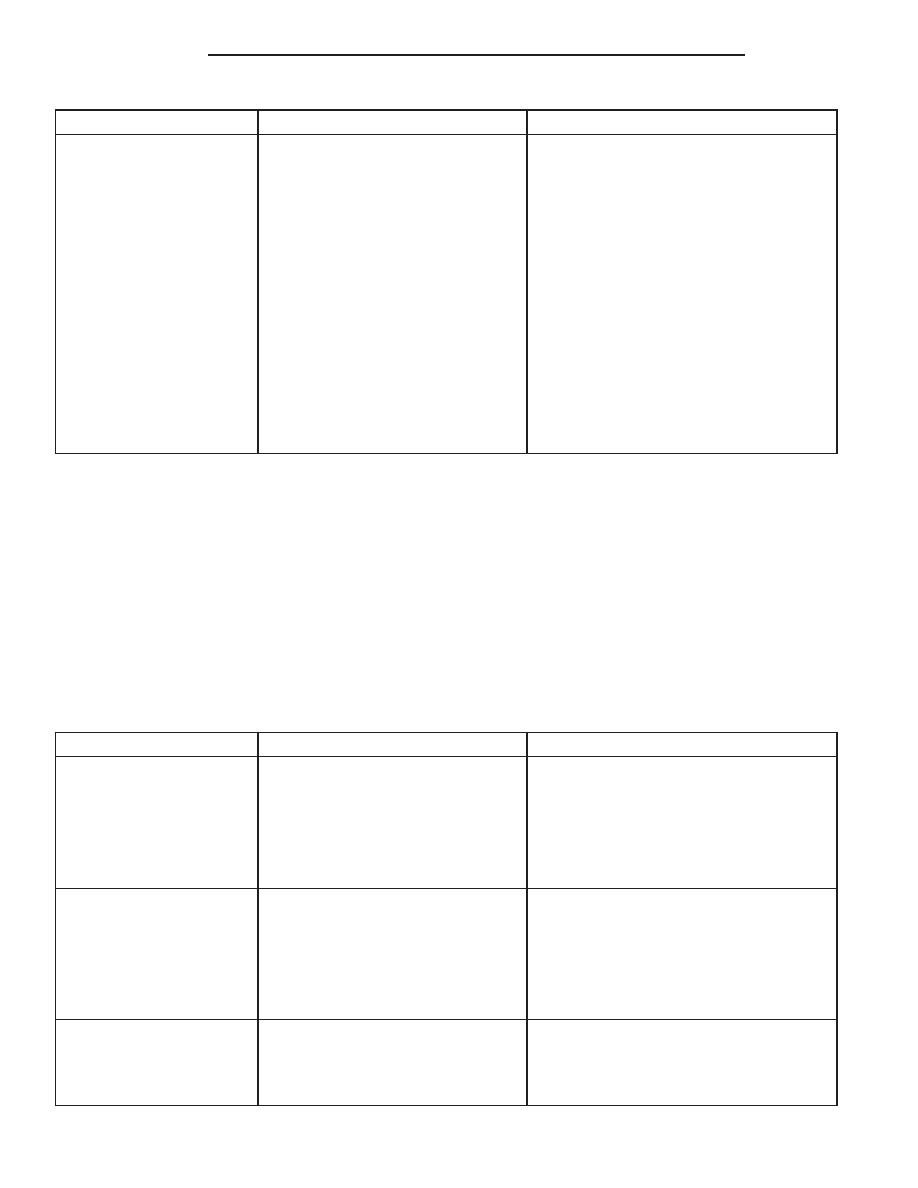
CONDITION
POSSIBLE CAUSES
CORRECTION
3. Steering column coupling worn,
broken or loose.
3. Replace steering column coupling.
4. Free play in steering column.
4. Check all components of the steering
system and repair or replace as required.
5. Worn control arm ball joints.
5. Replace ball joint or control arm as
required.
6. Loose steering knuckle to ball joint
stud pinch bolt.
6. Inspect pinch bolts, replace as
necessary, and tighten to specified torque.
7. Front wheel bearings loose or
worn.
7. Replace wheel bearing or knuckle as
necessary.
8. Loose outer tie rod ends.
8. Replace outer tie rod ends that have
excessive free play.
9. Loose inner tie rod ends.
9. Replace power steering gear.
10 Defective steering gear rotary
valve.
10. Replace power steering gear.
NOTE: * Steering shudder can be expected in new
vehicles and vehicles with recent steering system
repairs. Shudder should dissipate after the vehicle
has been driven several weeks.
NOTE: ** To evaluate this condition, it may be nec-
essary to disconnect the coupling at the base of the
steering column. Turn the steering wheel and feel or
listen for internal rubbing in steering column. To
avoid damaging the column clockspring, note the
following. Before disconnecting coupling, place
tires in the straight-ahead position and center steer-
ing wheel. Once disconnected, DO NOT rotate
steering wheel more than one revolution in either
direction and place steering wheel in original loca-
tion before reconnecting coupling. If this position is
lost, the steering column clockspring must be
re-centered following the procedure found within
the procedure for steering column installation in the
steering column section.
POWER STEERING FLUID
CONDITION
POSSIBLE CAUSES
CORRECTION
LOW FLUID LEVEL WITH
VISIBLE LEAK.
1. Loose power steering hose
fittings.
1. Tighten the fitting to its specified torque.
2. Damaged or missing fitting seal,
gasket, or O-ring.
2. Replace as necessary.
3. Power steering pump or power
steering gear leaking.
3. Repair or replace the leaking component
as required.
AERATED FLUID.*
1. Low fluid level.**
1. Fill power steering fluid reservoir to
proper level.
2. Air leak between power steering
fluid reservoir and pump.
2. Inspect for proper sealing. Replace the
power steering pump (with reservoir).
3. Cracked power steering pump
housing.
3. Replace the power steering pump.
RESERVOIR FLUID
OVERFLOW AND FLUID
IS MILKY IN COLOR
1. Water contamination.
1. Drain the power steering fluid from the
system. Flush the system with fresh clean
power steering fluid, drain, then refill to the
proper level.
19 - 8
STEERING
PL/SRT-4
STEERING (Continued)