Dodge Neon / Neon SRT-4. Manual - part 264


  Index      Dodge     Dodge Neon / Neon SRT-4 - service repair manual 2005 year


Search            


Content   ..  262  263  264  265   ..


Dodge Neon / Neon SRT-4. Manual - part 264


(7) Remove oil pick-up tube.
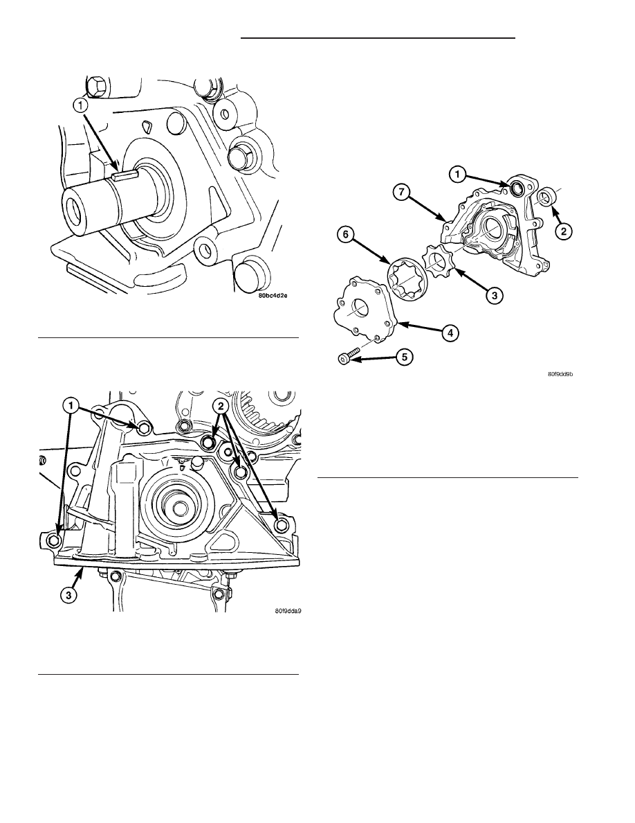
(8) Remove oil pump (Fig. 107) and front crank-

shaft seal.

DISASSEMBLY

(1)

Remove oil pump cover fasteners, and lift off

cover (Fig. 108).

(2)

Remove pump rotors (Fig. 108).

(3)

Wash all parts in a suitable solvent and

inspect carefully for damage or wear.

CLEANING

Clean all parts thoroughly.

Fig. 106 Crankshaft Key

1 - CRANKSHAFT KEY

Fig. 107 Oil Pump

1 - BOLTS
2 - BOLTS
3 - OIL PUMP

Fig. 108 Oil Pump

1 - O-RING
2 - FRONT CRANKSHAFT SEAL
3 - INNER ROTOR
4 - OIL PUMP COVER
5 - FASTENER
6 - OUTER ROTOR
7 - OIL PUMP BODY

9 - 150

ENGINE 2.4L DOHC TURBO

PL/SRT-4

OIL PUMP (Continued)

INSPECTION

(1) Inspect the mating surface of the oil pump.

Surface should be smooth. Replace pump cover if
scratched or grooved.

(2) Lay a straightedge across the pump cover sur-

face (Fig. 109). If a 0.025 mm (0.001 in.) feeler gauge
can be inserted between cover and straight edge,
cover should be replaced.

(3) Measure thickness and diameter of outer rotor.

If outer rotor thickness measures 10.699 mm (0.421
in.) or less (Fig. 110), or if the diameter is 85.924 mm
(3.383 in.) or less, replace outer rotor.

(4)

If inner rotor measures 10.699 mm (0.421 in.)

or less replace inner rotor (Fig. 111).

ASSEMBLY

(1) Assemble pump, using new parts as required.

Install the inner rotor with chamfer facing the
cast iron oil pump cover.

(2)

Prime oil pump before installation by filling

rotor cavity with engine oil.

(3)

Install cover and tighten fasteners to 13 N·m

(118 in. lbs.) (Fig. 108).

INSTALLATION

(1) Make sure all surfaces are clean and free of oil

and dirt.

(2) Apply Mopar

t Gasket Maker to oil pump as

shown in (Fig. 112). Install O-ring into oil pump body
discharge passage.

(3) Prime oil pump with engine oil before installa-

tion.

(4) Align oil pump rotor flats with flats on crank-

shaft. Install the oil pump to the block (Fig. 107).

CAUTION: To align, the front crankshaft seal MUST
be out of pump, or damage may result.

Fig. 109 Checking Oil Pump Cover Flatness

1 - STRAIGHT EDGE
2 - FEELER GAUGE
3 - OIL PUMP COVER

Fig. 110 Measuring Outer Rotor Thickness

Fig. 111 Measuring Inner Rotor Thickness

Fig. 112 Oil Pump Sealing

1 - O-RING
2 - SEALER LOCATION

PL/SRT-4

ENGINE 2.4L DOHC TURBO

9 - 151

OIL PUMP (Continued)

(5) Install new front crankshaft seal using Special

Tool 6780 (Fig. 113).

(6) Install crankshaft key (Fig. 106).

CAUTION: The crankshaft sprocket is set to a pre-
determined depth from the factory for correct tim-
ing belt tracking. If removed, use of Special Tool
6792 is required to set the sprocket to original
installation depth. An incorrectly installed sprocket
will result in timing belt and engine damage.

(7) Install crankshaft sprocket using Special Tool

6792 (Fig. 114).

(8) Install oil pump pick-up tube.
(9) Install oil pan (Refer to 9 - ENGINE/LUBRI-

CATION/OIL PAN - INSTALLATION).

(10) Install timing belt rear cover (Refer to 9 -

ENGINE/VALVE TIMING/TIMING BELT COVER(S)
- INSTALLATION).

(11) Install timing belt (Refer to 9 - ENGINE/

VALVE TIMING/TIMING BELT AND SPROCKETS -
INSTALLATION).

OIL JET

DESCRIPTION

The 2.4L Turbocharged engines are equipped with

four oil jets installed in the engine block. The oil jets
are provided engine oil pressure from the main oil
gallery. The oil jets are used to cool the pistons. An
integral check ball controls the flow of oil through
the oil jet (Fig. 115).

Fig. 113 Front Crankshaft Seal - Installation

1 - PROTECTOR
2 - SEAL
3 - SPECIAL TOOL 6780

Fig. 114 Crankshaft Sprocket - Installation

1 - SPECIAL TOOL 6792
2 - TIGHTEN NUT TO INSTALL

Fig. 115 Oil Jet - 2.4L Turbo

1 - PISTON ASSEMBLY
2 - ENGINE BLOCK
3 - OIL JET

9 - 152

ENGINE 2.4L DOHC TURBO

PL/SRT-4

OIL PUMP (Continued)

REMOVAL

(1) Remove crankshaft (Refer to 9 - ENGINE/EN-

GINE BLOCK/CRANKSHAFT - REMOVAL).

(2) Remove oil jet fastener (Fig. 116).

CAUTION: Do Not Pull on Oil Jet Tube

(3) Using pliers or other similar tool, pull oil jet

from engine block.

INSTALLATION

(1) Inspect oil jet o-ring (Fig. 117).
(2) Lightly coat o-ring with clean engine oil.
(3) Push oil jet into engine block until it is fully

seated.

CAUTION: Ensure oil jet is fully seated in engine
block before installing fastener. Do Not use the oil
jet fastener to draw the oil jet into the engine block.
Damage to oil jet may occur.

(4) Install oil jet fastener. Torque fastener to 12

N·m (105 in. lbs.) (Fig. 116).

(5) Install crankshaft (Refer to 9 - ENGINE/EN-

GINE BLOCK/CRANKSHAFT - INSTALLATION).

OIL COOLER & LINES

DESCRIPTION

An engine oil cooler is used on the 2.4L Turbo-

charged engine. The cooler is a coolant-to-oil type

and mounted between the oil filter and oil filter
adapter (Fig. 118).

REMOVAL

(1) Raise vehicle on hoist.
(2) Drain cooling system (Refer to 7 - COOLING/

ENGINE - STANDARD PROCEDURE).

(3) Disconnect oil cooler coolant hoses (Fig. 118).
(4) Remove oil filter.
(5) Remove oil cooler connector bolt (Fig. 119).
(6) Remove oil cooler.

Fig. 116 Oil Jet Fastener - 2.4L Turbo

1 - FASTENER - 12 N·m (105 in. lbs.)
2 - OIL JET
3 - ENGINE BLOCK
4 - CYLINDER WALL

Fig. 117 Oil Jet O-ring

1 - OIL JET
2 - O-RING

Fig. 118 Oil Cooler and Lines

1 - COOLANT TUBES
2 - COOLANT HOSES
3 - OIL FILTER
4 - OIL COOLER

PL/SRT-4

ENGINE 2.4L DOHC TURBO

9 - 153

OIL JET (Continued)


Content   ..  262  263  264  265   ..