Dodge Neon / Neon SRT-4. Manual - part 247


  Index      Dodge     Dodge Neon / Neon SRT-4 - service repair manual 2005 year


Search            


Content   ..  245  246  247  248   ..


Dodge Neon / Neon SRT-4. Manual - part 247


(3) Install camshaft sprocket retaining bolt. While

holding sprocket with Special Tools C-4687 and mod-
ified Adaptor C-4687-1, tighten attaching bolt to 115
N·m (85 ft. lbs.).

(4) Install timing belt tensioner/bracket assembly

(Refer to 9 - ENGINE/VALVE TIMING/TIMING
BELT TENSIONER ASSEMBLY - INSTALLATION).

(5) Install timing belt (Refer to 9 - ENGINE/

VALVE TIMING/TIMING BELT AND SPROCKETS -
INSTALLATION).

(6) Install front timing belt cover. Refer to FRONT

COVER

FRONT COVER

(1) Install front cover and tighten bolts to 12 N·m

(105 in. lbs.) (Fig. 143).

(2) Position engine mount bracket to its mounting

location. Hand start the upper two bolts of the
engine mount bracket (Fig. 142).

(3) Lower engine with jack.
(4) Install

lower

engine

mount

bracket

bolt.

Tighten bolt to 61 N·m (45 ft. lbs.) (Fig. 142).

(5) Raise engine with jack.
(6) Tighten upper engine mount bracket bolts to 61

N·m (45 ft. lbs.) (Fig. 142).

(7) Install power steering pump assembly.
(8) Lower engine with jack.
(9) Install right engine mount to engine mount

bracket through bolt. Tighten bolt to 118 N·m (87 ft.
lbs.) (Fig. 141).

(10) Remove jack from under engine.
(11) Raise vehicle on hoist.
(12) Install lower torque strut (Refer to 9 -

ENGINE/ENGINE MOUNTING/TORQUE STRUT -
INSTALLATION).

(13) Install

crankshaft

damper

(Refer

to

9

-

ENGINE/ENGINE BLOCK/VIBRATION DAMPER -
INSTALLATION).

(14) Install accessory drive belts (Refer to 7 -

COOLING/ACCESSORY

DRIVE/DRIVE

BELTS

-

INSTALLATION).

(15) Install accessory drive belt splash shield.
(16) Lower vehicle.
(17) Install upper torque strut (Refer to 9 -

ENGINE/ENGINE MOUNTING/TORQUE STRUT -
INSTALLATION).

(18) Install fastener securing ground strap to

engine mount bracket.

(19) Connect negative battery cable.
(20) Perform torque strut adjustment procedure

(Refer

to

9

-

ENGINE/ENGINE

MOUNTING/

TORQUE STRUT - ADJUSTMENTS).

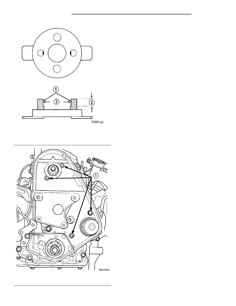
Fig. 144 Modification to Special Tool C-4687-1

1 - GRIND LOCATION
2 - 12.7 MM (1/2 IN.)
3 - 50.8 MM (2 IN.)

Fig. 145 Rear Timing Belt Cover

1 - BOLTS

9 - 82

ENGINE 2.0L SOHC

PL/SRT-4

TIMING BELT COVER(S) (Continued)

TIMING BELT AND
SPROCKETS

REMOVAL

TIMING BELT

(1) Remove front timing belt cover (Fig. 146)

(Refer to 9 - ENGINE/VALVE TIMING/TIMING
BELT COVER(S) - REMOVAL).

(2) Remove spark plugs (Refer to 8 - ELECTRI-

CAL/IGNITION

CONTROL/SPARK

PLUG

-

REMOVAL).

CAUTION: Align camshaft and crankshaft timing
marks before removing the timing belt by rotating
the engine CLOCKWISE with the crankshaft (Fig.
156).

(3) Loosen timing belt tensioner lock nut (Fig.

147).

(4) Insert a 6 mm Allen wrench into the hexagon

opening located on the top plate of the belt tensioner
pulley. Rotate the top plate CLOCKWISE until there

is enough slack in timing belt to allow for removal
(Fig. 147).

(5) Remove timing belt.

CAUTION: Do not rotate the camshaft once the tim-
ing belt has been removed or damage to valve com-
ponents may occur.

CAMSHAFT SPROCKET

(1) Remove timing belt (Refer to 9 - ENGINE/

VALVE TIMING/TIMING BELT AND SPROCKETS -
REMOVAL).

(2) Hold camshaft sprocket with Special Tools

C-4687 and modified Adaptor C-4687-1 (Fig. 148),
while removing attaching bolt.

NOTE: For Special Tool Identification, (Refer to 9 -
ENGINE - SPECIAL TOOLS).

(3) Remove camshaft sprocket.

Fig. 146 Timing Belt System - Mechanical Tensioner

1 - CAMSHAFT SPROCKET
2 - REAR TIMING BELT COVER
3 - MECHANICAL TIMING BELT TENSIONER ASSEMBLY
4 - WATER PUMP
5 - OIL PUMP BODY
6 - CRANKSHAFT SPROCKET

7 - TIMING BELT
8 - BOLT
9 - CRANKSHAFT DAMPER
10 - FRONT TIMING BELT COVER
11 - ACCESS PLUG
12 - CAMSHAFT BOLT AND WASHER

PL/SRT-4

ENGINE 2.0L SOHC

9 - 83

CRANKSHAFT SPROCKET

(1) Remove timing belt (Refer to 9 - ENGINE/

VALVE TIMING/TIMING BELT AND SPROCKETS -
REMOVAL)

(2) Remove the crankshaft sprocket using Special

Tool 6793 and insert C-4685-C2 (Fig. 149).

INSTALLATION

CRANKSHAFT SPROCKET

NOTE: Make sure the word “front” on the sprocket
is facing outward.

CAUTION: Use of Special Tool 6792 is required to
install the crankshaft sprocket to the proper depth.
Failure to use this tool will cause improper timing
belt tracking.

(1) Install the crankshaft sprocket (Fig. 150) using

Special Tool 6792.

Fig. 147 Timing Belt Removal

1 - CAMSHAFT TIMING MARKS
2 - LOCK NUT
3 - TOP PLATE
4 - 6mm ALLEN WRENCH
5 - CRANKSHAFT TIMING MARKS

Fig. 148 Modification to Special Tool C-4687-1

1 - GRIND LOCATION
2 - 12.7 MM (1/2 IN.)
3 - 50.8 MM (2 IN.)

Fig. 149 Crankshaft Sprocket Removal

1 - SPECIAL TOOL 6793
2 - SPECIAL TOOL C-4685–C2
3 - CRANKSHAFT SPROCKET

Fig. 150 Crankshaft Sprocket Installation

1 - SPECIAL TOOL 6792

9 - 84

ENGINE 2.0L SOHC

PL/SRT-4

TIMING BELT AND SPROCKETS (Continued)

CAMSHAFT SPROCKET

(1) Install

camshaft

sprocket.

While

holding

sprockets with Special Tools C-4687 and modified
Adaptor C-4687-1, tighten attaching bolt to 115 N·m
(85 ft. lbs.).

(2) Install timing belt (Refer to 9 - ENGINE/

VALVE TIMING/TIMING BELT AND SPROCKETS -
INSTALLATION).

TIMING BELT

(1) Set crankshaft sprocket to TDC by aligning the

sprocket with the arrow on the oil pump housing,
then back off to 3 notches before TDC (Fig. 151).

(2) Set camshaft to TDC by aligning mark on

sprocket with the arrow on the rear timing belt cover
(Fig. 152).

(3) Move crankshaft to 1/2 mark before TDC (Fig.

153) for belt installation.

(4) Install the timing belt. Starting at the crank-

shaft, go around the water pump sprocket, then
around the camshaft sprocket, and finally route the
back side of the timing belt around the timing belt
tensioner pulley.

(5) Move crankshaft sprocket to TDC to take up

belt slack.

(6) Insert a 6 mm Allen wrench into the hexagon

opening located on the top plate of the belt tensioner
pulley. Rotate the top plate COUNTERCLOCK-
WISE
. The tensioner pulley will move against the
belt and the tensioner setting notch will eventually
start to move clockwise. Watching the movement of
the setting notch, continue rotating the top plate
counterclockwise until the setting notch is aligned
with the spring tang (Fig. 154). Using the allen
wrench to prevent the top plate from moving, torque
the tensioner lock nut to 30 N·m (22 ft. lbs.). Setting
notch and spring tang should remain aligned after
lock nut is torqued.

(7) Remove allen wrench and torque wrench.

NOTE: Repositioning the crankshaft to the TDC
position must be done only during the CLOCKWISE
rotation movement. If TDC is missed, rotate a fur-
ther two revolutions until TDC is achieved. DO NOT
rotate crankshaft counterclockwise as this will
make verification of proper tensioner setting impos-
sible.

Fig. 151 Crankshaft Sprocket Timing

1 - TDC MARK

Fig. 152 Camshaft Timing Mark

1 - CAM SPROCKET TIMING MARK
2 - ARROW ON REAR COVER

Fig. 153 Adjusting Crankshaft Sprocket for Timing

Belt

1 - TDC REFERENCE MARK
2 - 1/2 NOTCH LOCATION
3 - TDC MARK

PL/SRT-4

ENGINE 2.0L SOHC

9 - 85

TIMING BELT AND SPROCKETS (Continued)


Content   ..  245  246  247  248   ..