Dodge Neon / Neon SRT-4. Manual - part 246


  Index      Dodge     Dodge Neon / Neon SRT-4 - service repair manual 2005 year


Search            


Content   ..  244  245  246  247   ..


Dodge Neon / Neon SRT-4. Manual - part 246


(9) Disconnect wiring at starter.
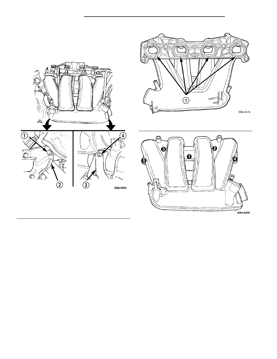
(10) Remove the intake manifold to lower support

bracket bolts (Fig. 133).

(11) Remove intake manifold screws and washers.

Discard the fasteners. Remove intake manifold.

INSPECTION

• Inspect manifold for cracks or distortions.

• Check for torn or missing O-rings at the mating

surface of the manifold (Fig. 134).

INSTALLATION

Before installing manifold. Clean all mating sur-

faces. Replace all O-ring gaskets with new gaskets
(Fig. 134). All intake manifold fasteners and washers
are to be discarded and NEW fasteners and washers
are to be used.

(1) Install intake manifold onto cylinder head and

tighten fasteners to 12 N·m (105 in. lbs.) in sequence
shown in (Fig. 135).

(2) Install

intake

manifold

to

lower

support

bracket bolts (Fig. 133). Tighten bolts to 11 N·m (95
in. lbs.).

(3) Remove covering from fuel injector holes and

insure the holes are clean. Install fuel rail assembly
to intake manifold. Tighten screws to 23 N·m (200 in.
lbs.).

(4) Connect PCV and brake booster hoses.
(5) Inspect quick connect fittings for damage,

replace if necessary (Refer to 14 - FUEL SYSTEM/
FUEL DELIVERY/QUICK CONNECT FITTING -
STANDARD PROCEDURE). Apply a light amount of
clean engine oil to fuel inlet tube. Connect fuel sup-
ply hose to fuel rail assembly. Check connection by
pulling on connector to insure it locked into position.

(6) Connect Manifold Absolute Pressure (MAP)

Sensor wiring connector (Fig. 131).

(7) Connect knock sensor connector, and wiring at

starter.

(8) Install inlet air duct to intake manifold and

throttle body. Tighten clamp to 3 N·m (30 in. lbs.).

(9) Connect negative cable to battery.
(10) With the DRB scan tool use ASD Fuel System

Test to pressurize system to check for leaks.

Fig. 133 Intake Manifold Lower Supports

1 - BOLT
2 - BRACKET
3 - BRACKET
4 - BOLT

Fig. 134 Intake Manifold Gaskets

1 - INTAKE MANIFOLD O-RING GASKETS

Fig. 135 Intake Manifold Tightening Sequence

9 - 78

ENGINE 2.0L SOHC

PL/SRT-4

INTAKE MANIFOLD (Continued)

CAUTION: When using the ASD Fuel System Test,
the Auto Shutdown (ASD) relay will remain ener-
gized for 7 minutes or until the ignition switch is
turned to the OFF position, or Stop All Test is
selected.

EXHAUST MANIFOLD

DESCRIPTION

The exhaust manifold is made of nodular cast iron

for strength and high temperatures. The manifold
attaches to the cylinder head.

OPERATION

The exhaust manifold collects the exhaust gasses

exiting the combustion chambers. Then it channels
the exhaust gasses to the exhaust pipe attached to
the manifold.

REMOVAL

(1) Disconnect negative cable from battery.
(2) Raise vehicle on hoist.
(3) Remove bolt attaching the wire harness heat

shield to the exhaust manifold support bracket (Fig.
136).

(4) Remove exhaust manifold support bracket (Fig.

137).

(5) Remove fasteners attaching exhaust system

flex joint to exhaust manifold flange. Move exhaust
system rearward to clear flange studs.

(6) Lower vehicle.
(7) Disconnect make-up air hose from rear of cyl-

inder head cover.

(8) Disconnect oxygen sensor connector and har-

ness clip.

(9) Remove heat shield attaching bolts (Fig. 138).

(10) Remove upper heat shield for access to mani-

fold bolts.

(11) Remove exhaust manifold bolts.
(12) Remove exhaust manifold from top of vehicle,

between the cylinder head and cowl.

CLEANING

(1) Discard gasket (if equipped) and clean all sur-

faces of manifold and cylinder head.

INSPECTION

(1) Inspect manifold gasket surfaces for flatness

with straight edge. Surface must be flat within 0.15
mm per 300 mm (0.006 in. per foot) of manifold
length.

Fig. 136 Wire Harness Heat Shield Bolt

1 - BOLT
2 - BRACKET
3 - HEAT SHIELD

Fig. 137 Exhaust Manifold Support Bracket

1 - BRACKET
2 - BOLT (M10) - 54 N·m (40 ft. lbs.)
3 - BOLT (M12) - 95 N·m (70 ft. lbs.)
4 - NUT - 28 N·m (250 in. lbs.)

Fig. 138 Exhaust Manifold Heat Shields

1 - BOLTS
2 - HEAT SHIELDS

PL/SRT-4

ENGINE 2.0L SOHC

9 - 79

INTAKE MANIFOLD (Continued)

(2) Inspect manifolds for cracks or distortion.

Replace manifold as necessary.

INSTALLATION

(1) Position exhaust manifold and gasket in place.
(2) Install exhaust manifold bolts and tighten in

sequence shown in (Fig. 139) to 23 N·m (200 in. lbs.).

(3) Position

lower

and

upper

heat

shield

on

exhaust manifold. Install heat shield bolts and
tighten to 11 N·m (95 in. lbs.) (Fig. 138).

(4) Connect oxygen sensor electrical connector and

harness clip.

(5) Connect make-up air hose on cylinder head

cover port.

(6) Raise vehicle.
(7) Install new flex joint to manifold flange gasket.
(8) Attach exhaust system to manifold flange and

tighten fasteners to 28 N·m (250 in. lbs.).

(9) Install exhaust manifold support bracket and

tighten fasteners (Fig. 137).

(10) Install bolt attaching wire harness heat shield

to support bracket (Fig. 136).

(11) Lower vehicle.
(12) Connect negative cable to battery.

VALVE TIMING

STANDARD PROCEDURE - VALVE TIMING
VERIFICATION

(1) Remove number one spark plug.
(2) Using a dial indicator, set number one cylinder

to TDC on the compression stroke.

(3) Remove the access plug from the front timing

belt cover (Fig. 143).

(4) Check

the

timing

mark

on

the

camshaft

sprocket. Mark should align with the arrow on the
timing belt rear cover (Fig. 140).

TIMING BELT COVER(S)

REMOVAL

FRONT COVER

(1) Disconnect negative battery cable.
(2) Remove fastener securing ground strap to

engine mount bracket.

(3) Remove upper torque strut (Refer to 9 -

ENGINE/ENGINE MOUNTING/TORQUE STRUT -
REMOVAL).

(4) Remove power steering/air conditioning com-

pressor drive belt (Refer to 7 - COOLING/ACCES-
SORY DRIVE/DRIVE BELTS - REMOVAL).

(5) Raise vehicle on hoist.
(6) Remove accessory drive belt splash shield.
(7) Remove generator drive belt (Refer to 7 -

COOLING/ACCESSORY

DRIVE/DRIVE

BELTS

-

REMOVAL).

(8) Remove crankshaft damper (Refer to 9 -

ENGINE/ENGINE BLOCK/VIBRATION DAMPER -
REMOVAL).

(9) Remove lower torque strut (Refer to 9 -

ENGINE/ENGINE MOUNTING/TORQUE STRUT -
REMOVAL).

(10) Lower vehicle.
(11) Position a jack under engine. Raise jack

enough to support engine weight.

(12) Remove right engine mount to engine mount

bracket through bolt (Fig. 141).

(13) Lower engine enough with jack to remove

lower engine mount bracket bolt (Fig. 142).

(14) Raise engine with jack to allow engine-to-body

clearance for engine mount bracket removal.

Fig. 139 Exhaust Manifold Tightening Sequence-

Typical

Fig. 140 Camshaft Timing Marks

1 - CAM SPROCKET TIMING MARK
2 - ARROW ON REAR COVER

9 - 80

ENGINE 2.0L SOHC

PL/SRT-4

EXHAUST MANIFOLD (Continued)

(15) Remove power steering pump assembly and

set aside. Do Not disconnect lines from pump.

(16) Remove the two remaining bolts securing

engine mount bracket to engine. Remove engine
mount bracket (Fig. 142).

(17) Remove the front timing belt cover fasteners.

Remove front timing belt cover (Fig. 143).

REAR COVER

(1) Remove

front

timing

belt

cover.

Refer

to

FRONT COVER.

(2) Remove timing belt (Refer to 9 - ENGINE/

VALVE TIMING/TIMING BELT AND SPROCKETS -
REMOVAL).

(3) Remove timing belt tensioner/bracket assembly

(Refer to 9 - ENGINE/VALVE TIMING/TIMING
BELT TENSIONER ASSEMBLY - REMOVAL).

(4) Hold camshaft sprocket with Special Tools

C-4687 and modified Adaptor C-4687-1 (Fig. 144),
while removing attaching bolt.

NOTE: For Special Tool Identification, (Refer to 9 -
ENGINE - SPECIAL TOOLS).

(5) Remove camshaft sprocket.
(6) Remove rear cover attaching bolts (Fig. 145).
(7) Remove rear cover (Fig. 145).

INSTALLATION

REAR COVER

(1) Install rear cover and tighten bolts to 12 N·m

(105 in. lbs.) (Fig. 145).

(2) Install the camshaft sprocket on the camshaft.

CAUTION: DO NOT use an impact wrench (or any
other air operated tool) for tightening the camshaft
sprocket bolt. Damage to the camshaft timing pin
can result. ONLY use a hand wrench while holding
camshaft sprocket with Special Tool.

Fig. 141 Right Engine Mount to Bracket

1 - THROUGH BOLT
2 - RIGHT ENGINE MOUNT
3 - ENGINE MOUNT BRACKET

Fig. 142 Engine Mount Bracket

1 - BOLTS
2 - ENGINE MOUNT BRACKET ASSEMBLY

Fig. 143 Front Timing Belt Cover

1 - ACCESS PLUG
2 - BOLTS

PL/SRT-4

ENGINE 2.0L SOHC

9 - 81

TIMING BELT COVER(S) (Continued)


Content   ..  244  245  246  247   ..