Dodge Neon / Neon SRT-4. Manual - part 245
(5)
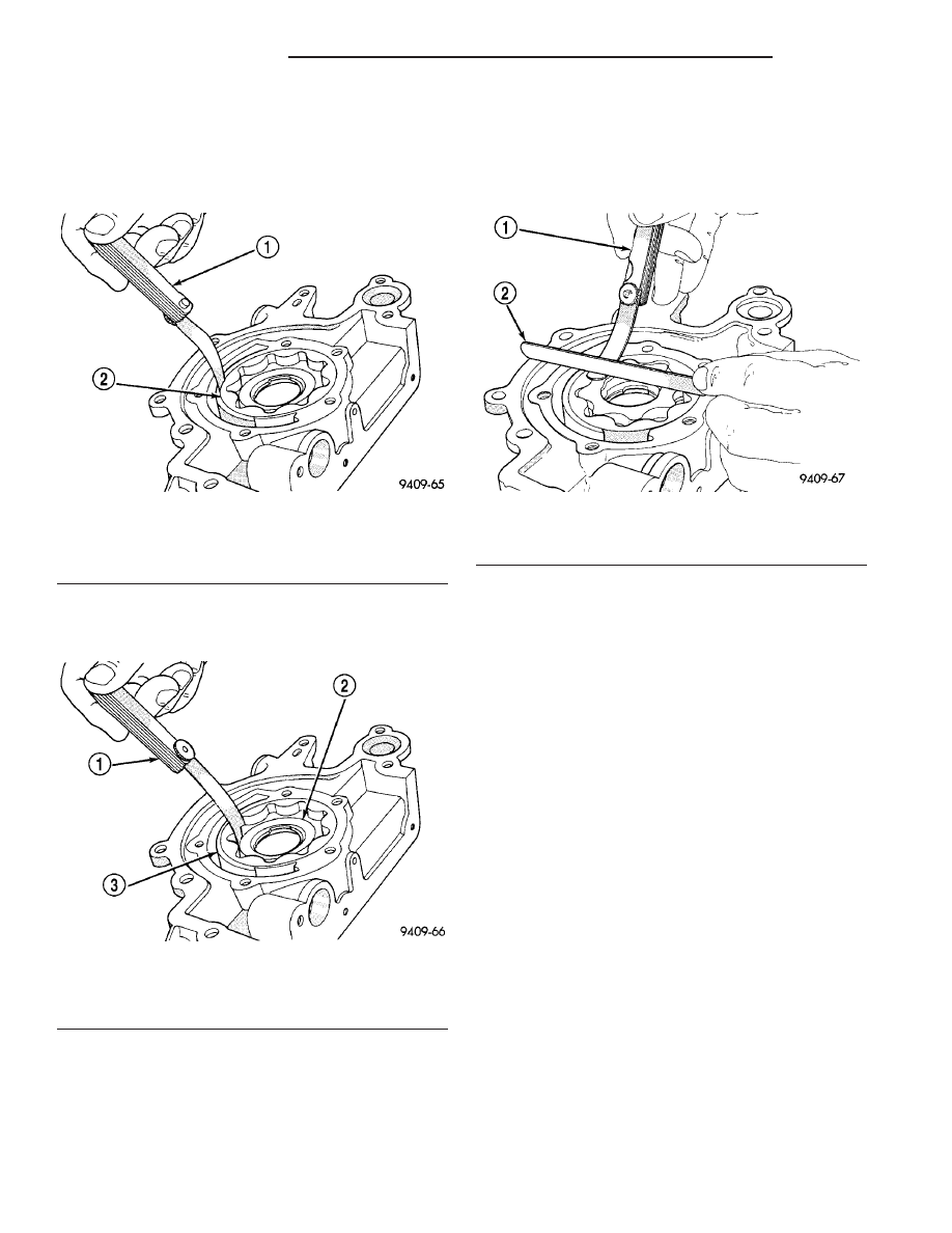
Slide outer rotor into pump housing, press to
one side with fingers and measure clearance between
rotor and housing (Fig. 122). If measurement is 0.39
mm (0.015 in.) or more, replace housing only if outer
rotor is in specification.
(6) Install inner rotor into pump housing. If clear-
ance between inner and outer rotors (Fig. 123) is
0.203 mm (0.008 in.) or more, replace both rotors.
(7) Place a straightedge across the face of the
pump housing, between bolt holes. If a feeler gauge
of 0.102 mm (0.004 inch) or more can be inserted
between rotors and the straightedge, replace pump
assembly (Fig. 124). ONLY if rotors are in specs.
(8) Inspect oil pressure relief valve plunger for
scoring and free operation in its bore. Small marks
may be removed with 400-grit wet or dry sandpaper.
(9) The relief valve spring has a free length of
approximately 60.7 mm (2.39 in.) it should test
between 18 and 19 pounds when compressed to 40.5
mm (1.60 in.). Replace spring that fails to meet spec-
ifications.
(10) If oil pressure is low and pump is within spec-
ifications, inspect for worn engine bearings, damaged
or missing oil pick-up tube O-ring, clogged oil pick-up
tube screen, clogged oil filter and stuck open pres-
sure relief valve or other reasons for oil pressure
loss.
ASSEMBLY
(1) Install oil pump rotors (Fig. 118).
(2) Install oil pump cover and screws (Fig. 118).
Tighten screws to 12 N·m (105 in. lbs.).
CAUTION: Oil pump pressure relief valve must be
installed as shown in (Fig. 117) or serious damage
may occur.
(3) Install spring and relief valve (Fig. 117).
(4) Install threaded plug and gasket to the oil
pump (Fig. 117). Tighten plug to 41 N·m (30 ft. lbs.).
Fig. 122 Measuring Outer Rotor Clearance in
Housing
1 - FEELER GAUGE
2 - OUTER ROTOR
Fig. 123 Measuring Clearance Between Rotors
1 - FEELER GAUGE
2 - INNER ROTOR
3 - OUTER ROTOR
Fig. 124 Measuring Clearance Over Rotors
1 - FEELER GAUGE
2 - STRAIGHT EDGE
9 - 74
ENGINE 2.0L SOHC
PL/SRT-4
OIL PUMP (Continued)