Dodge Neon / Neon SRT-4. Manual - part 85


  Index      Dodge     Dodge Neon / Neon SRT-4 - service repair manual 2005 year


Search            


Content   ..  83  84  85  86   ..


Dodge Neon / Neon SRT-4. Manual - part 85


(6) Ensure the proper starter alignment before

tightening the starter mounting bolts to 54 N·m (40
ft. lbs.) torque.

(7) Reposition the air cleaner box into postion and

connect the inlet hose from intake manifold (Fig. 10).

(8) Connect negative battery cable (Fig. 7).

STARTER MOTOR 2.0L 4 SPD
AUTO

REMOVAL - 2.0L AUTOMATIC TRANSMISSION

(1) Disconnect the negative battery cable.
(2) Remove the air cleaner box, refer to the air

cleaner box removal/installation in this section.

(3) Remove the 2 upper bracket bolts for the

intake support (Fig. 15).

(4) Raise vehicle and support.
(5) Remove the oil pan support bracket (Fig. 16).
(6) Remove the intake support bracket (Fig. 17).
(7) Disconnect the battery cable and solenoid con-

nection from the starter.

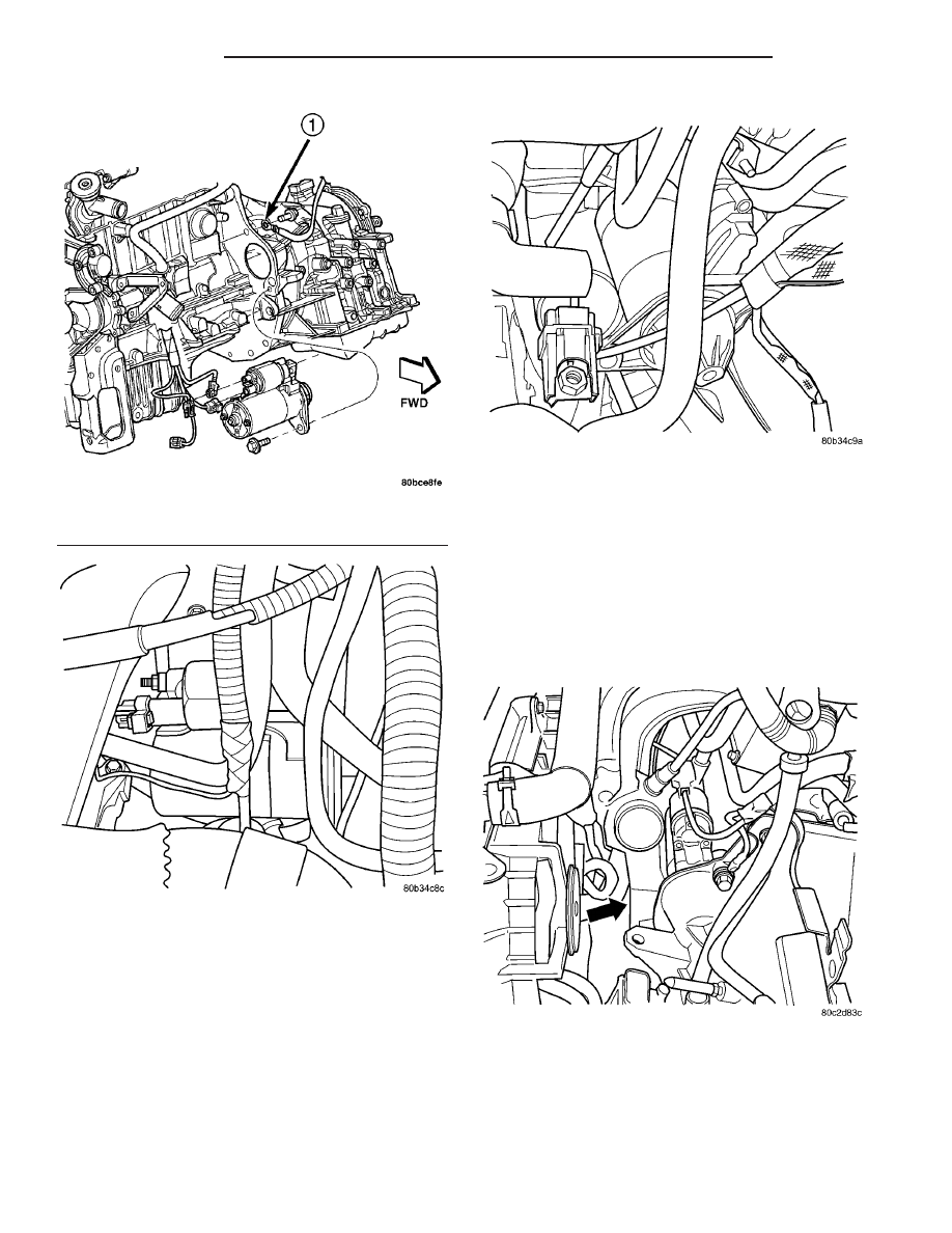
Fig. 12 Starter Mounting/Location

1 - NEGATIVE BATTERY CABLE

Fig. 13 STARTER ELECTRICAL CONNECTION

Fig. 14 STARTER

Fig. 15 INTAKE SUPPORT BRACKET

8F - 36

STARTING

PL/SRT-4

STARTER MOTOR - 2.0L HIGH OUTPUT (Continued)

(8) Remove the starter bolts.
(9) Remove starter.

INSTALLATION - 2.0L AUTOMATIC
TRANSMISSION

(1) Install starter.
(2) Install the starter bolts.
(3) Connect the battery cable and solenoid connec-

tion from the starter.

(4) Install the intake support bracket (Fig. 17).
(5) Install the oil pan support bracket (Fig. 16).
(6) Lower vehicle.
(7) Install the 2 upper bracket bolts for the intake

support (Fig. 15).

(8) Install the air cleaner box, refer to the air

cleaner box removal/installation in this section.

(9) Connect the negative battery cable.

STARTER MOTOR - 2.4L SRT-4

REMOVAL - 2.4L SRT-4

(1) Disconnect and isolate the battery negative

cable (Fig. 18).

(2) Remove the air cleaner box, refer to the

Engine/Air Intake/Air Cleaner Assembly for more
information.

(3) Remove the throttle body, refer to the Throttle

body in the Fuel/Injection for more information.

(4) Remove the upper mounting bolt and ground

wire (Fig. 19).

(5) Raise vehicle and support.
(6) Disconnect the battery positive cable from

starter (Fig. 20).

(7) Disconnect the solenoid connector from starter

(Fig. 20).

(8) Remove the middle starter mounting bolt (Fig.

20).

(9) Loosen the upper bolt for the intake manifold

support and swing bracket out of the way (Fig. 21).

(10) Remove the lower mounting bolt.
(11) Remove the starter (Fig. 22).

Fig. 16 OIL PAN BRACKET

Fig. 17 INTAKE SUPPORT BRACKET LOWER

BOLTS

Fig. 18 Battery Negative Cable Remove/Install

1 - NEGATIVE CABLE
2 - NEGATIVE BATTERY POST

PL/SRT-4

STARTING

8F - 37

STARTER MOTOR 2.0L 4 SPD AUTO (Continued)

INSTALLATION - 2.4L SRT-4

(1) Install the starter (Fig. 22).
(2) Install the lower mounting bolt.
(3) Loosen upper bolt for the intake manifold sup-

port bracket and swing bracket back into place (Fig.
21).

(4) Install the middle starter mounting bolt (Fig.

20).

(5) Tighten the intake manifold support bracket

bolt.

(6) Tightening the starter mounting bolts to 54

N·m (40 ft. lbs.) torque

(7) Connect the solenoid connector to starter (Fig.

20).

(8) Connect the battery positive cable to starter

(Fig. 20) Tighten the captive nut to 10 N·m (90 in.
lbs.).

(9) Lower vehicle.
(10) Install the upper mounting bolt and ground

wire (Fig. 19) and tighten the starter mounting bolt
to 54 N·m (40 ft. lbs.) torque.

(11) Install the throttle body, refer to the Fuel/In-

jection/Throttle Body for more information.

(12) Install the air cleaner box, refer to the

Engine/Air Intake/Air Cleaner Assembly for more
information.

(13) Connect the battery negative cable (Fig. 18).

Fig. 19 MOUNTING BOLT & GROUND WIRE

Fig. 20 MOUNTING BOLTS & ELECTRICAL

CONNECTIONS

1 - Mounting Bolts
2 - Electrical Connections

Fig. 21 INTAKE BRACKET

Fig. 22 STARTER REMOVE/INSTALL

8F - 38

STARTING

PL/SRT-4

STARTER MOTOR - 2.4L SRT-4 (Continued)

STARTER MOTOR RELAY

DESCRIPTION

The Starter Relay is a micro relay located in the

Power Distribution Center (PDC), positioned in the
left front corner of the engine compartment.

OPERATION

As battery power is applied to the relay from the

ignition switch, battery power is applied to the
starter motor through the relay to the starter sole-
noid.

REMOVAL

The relay is located in the Power Distribution Cen-

ter (PDC). Refer to the PDC cover for relay location.

STARTER SOLENOID

DESCRIPTION

The Starter Solenoid is mounted directly to the

Starter Motor.

OPERATION

The Starter Solenoid is a switching device used to

activate the high amperage starter motor circuit from
a low amperage control circuit.

PL/SRT-4

STARTING

8F - 39


Content   ..  83  84  85  86   ..