Dodge Neon / Neon SRT-4. Manual - part 84
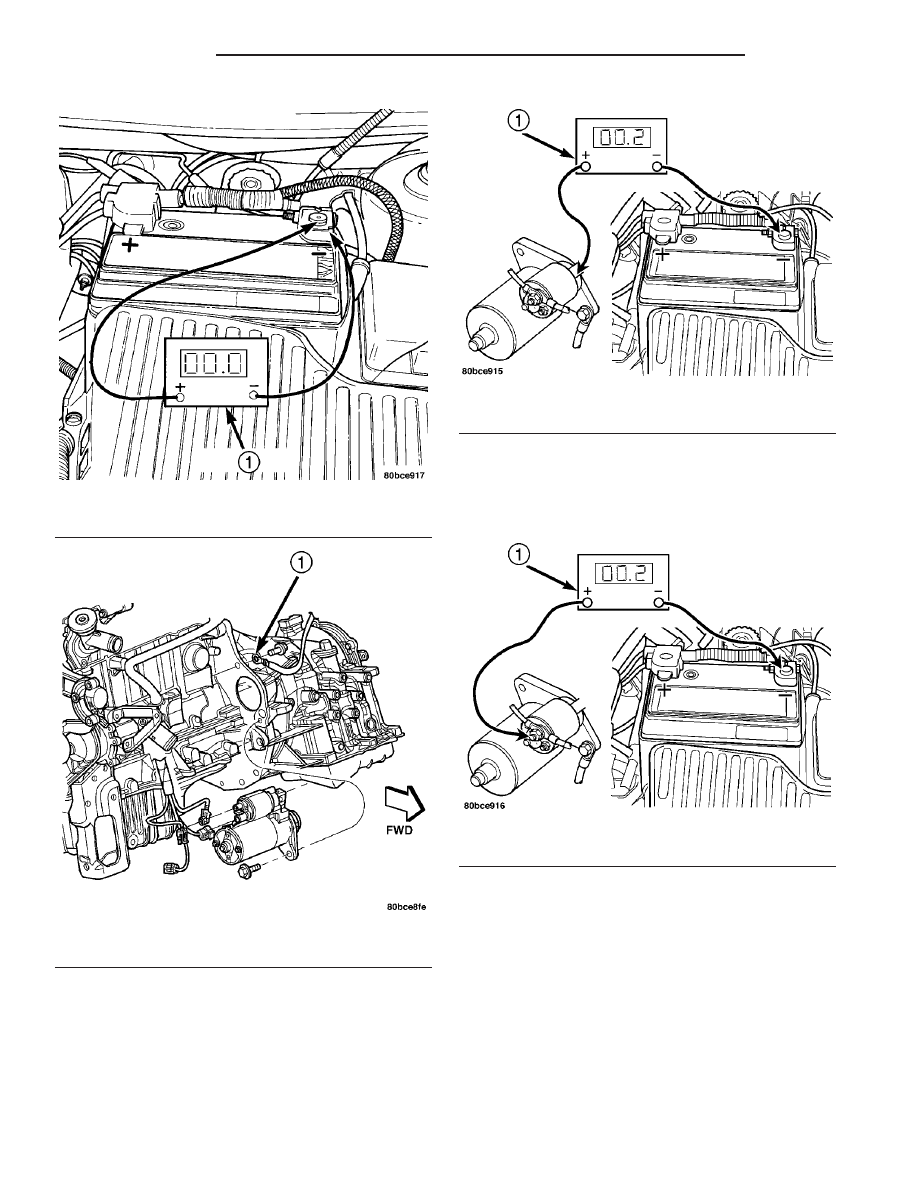
(3) Connect positive voltmeter lead to the starter
motor housing and the negative lead to the battery
negative terminal (Fig. 3). Hold the ignition switch
key in the START position. If voltage reads above 0.2
volt, correct poor starter to engine ground.
(a) Connect the positive voltmeter lead to the
battery positive terminal, and negative lead to bat-
tery cable terminal on starter solenoid (Fig. 4).
Rotate and hold the ignition switch in the START
position. If voltage reads above 0.2 volt, correct
poor contact at battery cable to solenoid connec-
tion. If reading is still above 0.2 volt after correct-
ing poor contacts, replace battery positive cable.
(b) If resistance tests do not detect feed circuit
failures, replace the starter motor.
DIAGNOSIS AND TESTING - FEED CIRCUIT
The following procedure will require a suitable
volt-ampere tester (Fig. 5).
CAUTION:
Before performing any starter tests, the ignition and
fuel systems must be disabled.
(1) Check battery before performing this test. Bat-
tery must be fully charged.
Fig. 1 Battery Connection Resistance
1 - VOLTMETER
Fig. 2 Ground Circuit Resistance
1 - NEGATIVE BATTERY CABLE
Fig. 3 Starter Motor Ground Resistance
1 - VOLTMETER
Fig. 4 Battery Positive Cable Resistance
1 - VOLTMETER
8F - 32
STARTING
PL/SRT-4
STARTING (Continued)