Dodge Neon / Neon SRT-4. Manual - part 77


  Index      Dodge     Dodge Neon / Neon SRT-4 - service repair manual 2005 year


Search            


Content   ..  75  76  77  78   ..


Dodge Neon / Neon SRT-4. Manual - part 77


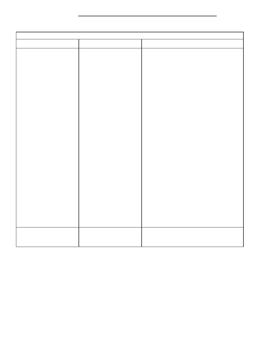
BATTERY SYSTEM DIAGNOSIS

CONDITION

POSSIBLE CAUSES

CORRECTION

THE BATTERY STATE OF
CHARGE CANNOT BE
MAINTAINED.

1. The battery has an
incorrect size or rating for
this vehicle.

1. Refer to Battery System Specifications for the
proper specifications. Replace an incorrect
battery, as required.

2. The battery terminal
connections are loose or
corroded.

2. Refer to Battery Cable for the proper cable
diagnosis and testing procedures. Clean and
tighten the battery terminal connections, as
required.

3. The electrical system
ignition-off draw is excessive.

3. Refer to the IGNITION-OFF DRAW TEST
Standard Procedure for the proper test
procedures. Repair the faulty electrical system, as
required.

4. The battery is faulty.

4. Test the battery using the Micro 420 battery
tester. Refer to Standard Procedures for
additional test procedures. Replace the faulty
battery, as required.

5. The starting system is
faulty.

5. Determine if the starting system is performing
to specifications. Refer to Starting System for the
proper starting system diagnosis and testing
procedures. Repair the faulty starting system, as
required.

6. The charging system is
faulty.

6. Determine if the charging system is performing
to specifications. Refer to Charging System for
additional charging system diagnosis and testing
procedures. Repair the faulty charging system, as
required.

7. Electrical loads exceed the
output of the charging
system.

7. Inspect the vehicle for aftermarket electrical
equipment which might cause excessive electrical
loads.

8. Slow driving or prolonged
idling with high-amperage
draw systems in use.

8. Advise the vehicle operator, as required.

THE BATTERY WILL NOT
ACCEPT A CHARGE.

1. The battery is faulty.

1. Test the battery using the Micro 420 battery
tester. Charge or replace the faulty battery, as
required.

ABNORMAL BATTERY DISCHARGING

Any of the following conditions can result in abnor-

mal battery discharging:

1. A faulty or incorrect charging system compo-

nent. Refer to Charging System for additional charg-
ing system diagnosis and testing procedures.

2. A faulty or incorrect battery. Use Micro 420 bat-

tery tester and refer to Battery System for additional
battery diagnosis and testing procedures.

3. A faulty circuit or component causing excessive

ignition-off draw.

4. Electrical loads that exceed the output of the

charging system. This can be due to equipment

installed after manufacture, or repeated short trip
use.

5. A faulty or incorrect starting system component.

Refer to Starting System for the proper starting sys-
tem diagnosis and testing procedures.

6. Corroded or loose battery posts and/or terminal

clamps.

7. Slow driving speeds (heavy traffic conditions) or

prolonged idling, with high-amperage draw systems
in use.

CLEANING

The following information details the recommended

cleaning procedures for the battery and related com-

8F - 4

BATTERY SYSTEM

PL/SRT-4

BATTERY SYSTEM (Continued)

ponents. In addition to the maintenance schedules
found in this service manual and the owner’s man-
ual, it is recommended that these procedures be per-
formed any time the battery or related components
must be removed for vehicle service.

(1) Clean the battery cable terminal clamps of all

corrosion. Remove any corrosion using a wire brush
or a post and terminal cleaning tool, and a sodium
bicarbonate (baking soda) and warm water cleaning
solution (Fig. 1).

(2) Clean the battery tray and battery hold down

hardware of all corrosion. Remove any corrosion
using a wire brush and a sodium bicarbonate (baking
soda) and warm water cleaning solution. Paint any
exposed bare metal.

(3) If the removed battery is to be reinstalled,

clean the outside of the battery case and the top
cover with a sodium bicarbonate (baking soda) and
warm water cleaning solution using a stiff bristle
parts cleaning brush to remove any acid film (Fig. 2).
Rinse the battery with clean water. Ensure that the
cleaning solution does not enter the battery cells
through the vent holes. If the battery is being
replaced, refer to Battery System Specifications for
the factory-installed battery specifications. Confirm
that the replacement battery is the correct size and
has the correct ratings for the vehicle.

(4) If the vehicle is so equipped, clean the battery

thermal guard with a sodium bicarbonate (baking
soda) and warm water cleaning solution using a stiff
bristle parts cleaning brush to remove any acid film.

(5) Clean any corrosion from the battery terminal

posts with a wire brush or a post and terminal
cleaner, and a sodium bicarbonate (baking soda) and
warm water cleaning solution (Fig. 3).

Fig. 1 Clean Battery Cable Terminal Clamp - Typical

1 - TERMINAL BRUSH
2 - BATTERY CABLE

Fig. 2 Clean Battery - Typical

1 - CLEANING BRUSH
2 - WARM WATER AND BAKING SODA SOLUTION
3 - BATTERY

Fig. 3 Clean Battery Terminal Post - Typical

1 - TERMINAL BRUSH
2 - BATTERY CABLE
3 - BATTERY

PL/SRT-4

BATTERY SYSTEM

8F - 5

BATTERY SYSTEM (Continued)

INSPECTION

The following information details the recommended

inspection procedures for the battery and related
components. In addition to the maintenance sched-
ules found in this service manual and the owner’s
manual, it is recommended that these procedures be
performed any time the battery or related compo-
nents must be removed for vehicle service.

(1) Inspect the battery cable terminal clamps for

damage. Replace any battery cable that has a dam-
aged or deformed terminal clamp.

(2) Inspect the battery tray and battery holddown

hardware for damage. Replace any damaged parts.

(3) Slide the thermal guard off of the battery case.

Inspect the battery case for cracks or other damage
that could result in electrolyte leaks. Also, check the
battery terminal posts for looseness. Batteries with
damaged cases or loose terminal posts must be
replaced.

(4) Inspect the battery thermal guard for tears,

cracks, deformation or other damage. Replace any
battery thermal guard that has been damaged.

(5) Inspect the battery built-in test indicator sight

glass for an indication of the battery condition. If the
battery is discharged, charge as required. Refer to
Standard Procedures for the proper battery built-in
indicator test procedures. Also refer to Standard Pro-
cedures for the proper battery charging procedures.

SPECIFICATIONS

SPECIFICATIONS

The battery Group Size number, the Cold Cranking

Amperage (CCA) rating, and the Reserve Capacity

(RC) rating or Ampere-Hours (AH) rating can be
found on the original equipment battery label. Be
certain that a replacement battery has the correct
Group Size number, as well as CCA, and RC or AH
ratings that equal or exceed the original equipment
specification for the vehicle being serviced. Battery
sizes and ratings are discussed in more detail below.

• Group Size - The outside dimensions and ter-

minal placement of the battery conform to standards
established by the Battery Council International
(BCI). Each battery is assigned a BCI Group Size
number to help identify a correctly-sized replace-
ment.

• Cold Cranking Amperage - The Cold Crank-

ing Amperage (CCA) rating specifies how much cur-
rent (in amperes) the battery can deliver for thirty
seconds at -18° C (0° F). Terminal voltage must not
fall below 7.2 volts during or after the thirty second
discharge period. The CCA required is generally
higher as engine displacement increases, depending
also upon the starter current draw requirements.

• Reserve Capacity - The Reserve Capacity (RC)

rating specifies the time (in minutes) it takes for bat-
tery terminal voltage to fall below 10.5 volts, at a
discharge rate of 25 amperes. RC is determined with
the battery fully-charged at 26.7° C (80° F). This rat-
ing estimates how long the battery might last after a
charging system failure, under minimum electrical
load.

• Ampere-Hours - The Ampere-Hours (AH) rat-

ing specifies the current (in amperes) that a battery
can deliver steadily for twenty hours, with the volt-
age in the battery not falling below 10.5 volts. This
rating is also sometimes identified as the twenty-
hour discharge rating.

BATTERY CLASSIFICATIONS & RATINGS

Part Number

BCI Group Size

Classification

Cold Cranking

Amperage

Reserve

Capacity

Ampere -

Hours

Load Test

Amperage

0503327

26R

450

80 Minutes

48

225

8F - 6

BATTERY SYSTEM

PL/SRT-4

BATTERY SYSTEM (Continued)

TORQUE

DESCRIPTION

. . . . . . . . . . . . . . . . . . . . TORQUE

Battery Hold Down Bolt Clamp Bolt . . 200 ± 20 in.

lbs.

Battery Mount Fastener . . . . . . . . . 200 ± 20 in. lbs.

SPECIAL TOOLS

BATTERY SYSTEM SPECIAL TOOLS

BATTERY

DESCRIPTION

From the factory, most vehicles are equipped with

a maintenance-free battery, and others with a low-
maintenance battery.

Maintenance-free

batteries

have

non-removable

battery vent caps (Fig. 4). Water cannot be added to
this battery. Under normal service the composition of
this battery reduces gassing and water loss at nor-
mal charge rates. If the battery electrolyte level
becomes low, this battery must be replaced.

Low-maintenance batteries have removable battery

cell caps. Water can be added to this battery. Under
normal

service

the

composition

of

this

battery

reduces gassing and water loss at normal charge
rates.

The battery is a device used to store electrical

energy potential in a chemical form. When an electri-
cal load is applied to the battery terminals, an elec-

trochemical reaction occurs within the battery. This
reaction causes the battery to discharge electrical
current.

The battery is made up of six individual cells that

are connected in series. Each cell contains positive
charged plate groups made of lead oxide, and nega-
tively charged plate groups made of sponge lead. The
dissimilar metal plates are submerged in a sulfuric
acid and water solution called an electrolyte.

OPERATION

The battery is designed to store electrical energy in

a chemical form. When an electrical load is applied to
the terminals of the battery, an electrochemical reac-
tion occurs. This reaction causes the battery to dis-
charge electrical current from its terminals. As the
battery discharges, a gradual chemical change takes
place within each cell. The sulfuric acid in the elec-
trolyte combines with the plate materials, causing
both plates to slowly change to lead sulfate. At the
same time, oxygen from the positive plate material
combines with hydrogen from the sulfuric acid, caus-
ing the electrolyte to become mainly water. The
chemical changes within the battery are caused by
the movement of excess or free electrons between the
positive and negative plate groups. This movement of
electrons

produces

a

flow

of

electrical

current

through the load device attached to the battery ter-
minals.

As the plate materials become more similar chem-

ically, and the electrolyte becomes less acid, the volt-
age potential of each cell is reduced. However, by

Micro 420 Battery Tester

Fig. 4 Maintenance Free Battery

1 - POSITIVE POST
2 - VENT
3 - TEST INDICATOR
4 - VENT
5 - NEGATIVE POST
6 - PLATE GROUPS
7 - ELECTROLYTE LEVEL
8 - GREEN BALL
9 - MAINTENANCE FREE BATTERY

PL/SRT-4

BATTERY SYSTEM

8F - 7

BATTERY SYSTEM (Continued)


Content   ..  75  76  77  78   ..