Dodge Neon / Neon SRT-4. Manual - part 78


  Index      Dodge     Dodge Neon / Neon SRT-4 - service repair manual 2005 year


Search            


Content   ..  76  77  78  79   ..


Dodge Neon / Neon SRT-4. Manual - part 78


charging the battery with a voltage higher than that
of the battery itself, the battery discharging process
is reversed. Charging the battery gradually changes
the sulfated lead plates back into sponge lead and
lead dioxide, and the water back into sulfuric acid.
This action restores the difference in the electron
charges deposited on the plates, and the voltage
potential of the battery cells. For a battery to remain
useful, it must be able to produce high-amperage cur-
rent over an extended period. A battery must also be
able to accept a charge, so that its voltage potential
may be restored.

The battery is vented to release excess hydrogen

gas that is created when the battery is being charged
or discharged. However, even with these vents,
hydrogen gas can collect in or around the battery. If
hydrogen gas is exposed to flame or sparks, it may
ignite. If the electrolyte level is low, the battery may
arc internally and explode. If the battery is equipped
with removable cell caps, add distilled water when-
ever the electrolyte level is below the top of the
plates. If the battery cell caps cannot be removed, the
battery must be replaced if the electrolyte level
becomes low.

DIAGNOSIS AND TESTING - BATTERY

The battery must be completely charged and the

terminals should be properly cleaned and inspected
before diagnostic procedures are performed. Refer to
Battery System Cleaning for the proper cleaning pro-
cedures, and Battery System Inspection for the
proper battery inspection procedures. Refer to Stan-
dard Procedures for the proper battery charging pro-
cedures.

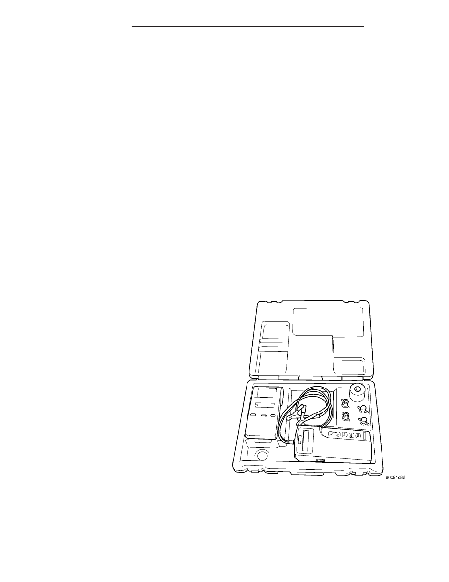
MICRO 420 ELECTRICAL SYSTEM TESTER

The Micro420 automotive battery and charging

system tester is designed to help the dealership tech-
nicians diagnose the cause of a defective battery or
charging system. Follow the instruction manual sup-
plied with the tester to properly diagnose a vehicle. If
the instruction manual is not available refer to the
standard procedure in this section, which includes
the directions for using the Micro420 electrical sys-
tem tester.

WARNING: IF THE BATTERY SHOWS SIGNS OF
FREEZING, LEAKING OR LOOSE POSTS, DO NOT
TEST, ASSIST-BOOST, OR CHARGE. THE BATTERY
MAY ARC INTERNALLY AND EXPLODE. PERSONAL
INJURY AND/OR VEHICLE DAMAGE MAY RESULT.

WARNING: EXPLOSIVE HYDROGEN GAS FORMS IN
AND AROUND THE BATTERY. DO NOT SMOKE,
USE FLAME, OR CREATE SPARKS NEAR THE BAT-

TERY. PERSONAL INJURY AND/OR VEHICLE DAM-
AGE MAY RESULT.

WARNING: THE BATTERY CONTAINS SULFURIC
ACID, WHICH IS POISONOUS AND CAUSTIC. AVOID
CONTACT WITH THE SKIN, EYES, OR CLOTHING.
IN THE EVENT OF CONTACT, FLUSH WITH WATER
AND CALL A PHYSICIAN IMMEDIATELY. KEEP OUT
OF THE REACH OF CHILDREN.

A battery that will not accept a charge is faulty,

and

must

be

replaced.

Further

testing

is

not

required. A fully-charged battery must be load tested
to determine its cranking capacity. A battery that is
fully-charged, but does not pass the load test, is
faulty and must be replaced.

NOTE: Completely discharged batteries may take
several hours to accept a charge. Refer to Standard
Procedures for the proper battery charging proce-
dures.

STANDARD PROCEDURE

STANDARD PROCEDURE - USING MICRO 420
BATTERY TESTER

Always use the Micro 420 Instruction Manual that

was supplied with the tester as a reference. If the
Instruction Manual is not available the following pro-
cedure can be used:

Fig. 5 Micro 420 Battery Tester

8F - 8

BATTERY SYSTEM

PL/SRT-4

BATTERY (Continued)

WARNING: ALWAYS

WEAR APPROPRIATE

EYE

PROTECTION AND USE EXTREME CAUTION WHEN
WORKING WITH BATTERIES.

BATTERY TESTING

(1) If testing the battery OUT-OF-VEHICLE, clean

the battery terminals with a wire brush before test-
ing. If the battery is equipped with side post termi-
nals, install and tighten the supplied lead terminal
stud adapters. Do not use steel bolts. Failure to prop-
erly install the stud adapters, or using stud adapters
that are dirty or worn-out may result in false test
readings.

(2) If testing the battery IN-THE-VEHICLE, make

certain all of the vehicle accessory loads are OFF,
including the ignition. The preferred test position
is at the battery terminal
. If the battery is not
accessible, you may test using both the positive and
negative jumper posts. Select TESTING AT JUMPER
POST when connecting to that location.

(3) Connect the tester (Fig. 5) to the battery or

jumper posts, the red clamp to positive (+) and the
black clamp to negative (–).

(4) Using the ARROW key select in or out of vehi-

cle testing and press ENTER to make a selection.

(5) If not selected, choose the Cold Cranking Amp

(CCA) battery rating. Or select the appropriate bat-
tery rating for your area (see menu). The tester will
then run its self programmed test of the battery and
display the results. Refer to the test result table
noted below.

CAUTION: If REPLACE BATTERY is the result of the
test, this may mean a poor connection between the
vehicle’s cables and battery exists. After discon-
necting the vehicle’s battery cables from the bat-
tery, retest the battery using the OUT-OF-VEHICLE
test before replacing.

(6) While viewing the battery test result, press the

CODE button and the tester will prompt you for the
last 4 digits of the VIN. Use the UP/DOWN arrow
buttons to scroll to the correct character; then press
ENTER to select and move to the next digit. Then
press the ENTER button to view the SERVICE
CODE. Pressing the CODE button a second time will
return you to the test results.

BATTERY TEST RESULTS

GOOD BATTERY

Return to service

GOOD - RECHARGE

Fully charge battery and

return to service

CHARGE & RETEST

Fully charge battery and

retest battery

BATTERY TEST RESULTS

REPLACE BATTERY

Replace the battery and

retest complete system

BAD-CELL REPLACE

Replace the battery and

retest complete system

NOTE: The SERVICE CODE is required on every
warranty claim submitted for battery replacement.

STANDARD PROCEDURE - BATTERY
CHARGING

Battery charging is the means by which the bat-

tery can be restored to its full voltage potential. A
battery is fully-charged when:

• Micro 420 electrical system tester indicates bat-

tery is OK.

• All of the battery cells are gassing freely during

battery charging.

• Three hydrometer tests, taken at one-hour inter-

vals, indicate no increase in the temperature-cor-
rected specific gravity of the battery electrolyte.

• Open-circuit voltage of the battery is 12.4 volts

or above.

WARNING: NEVER EXCEED TWENTY AMPERES
WHEN CHARGING A COLD (-1° C [30° F] OR
LOWER) BATTERY. THE BATTERY MAY ARC INTER-
NALLY AND EXPLODE. PERSONAL INJURY AND/OR
VEHICLE DAMAGE MAY RESULT.

WARNING: IF THE BATTERY SHOWS SIGNS OF
FREEZING, LEAKING, LOOSE POSTS, DO NOT
TEST, ASSIST-BOOST, OR CHARGE. THE BATTERY
MAY ARC INTERNALLY AND EXPLODE. PERSONAL
INJURY AND/OR VEHICLE DAMAGE MAY RESULT.

WARNING: EXPLOSIVE HYDROGEN GAS FORMS IN
AND AROUND THE BATTERY. DO NOT SMOKE,
USE FLAME, OR CREATE SPARKS NEAR THE BAT-
TERY. PERSONAL INJURY AND/OR VEHICLE DAM-
AGE MAY RESULT.

WARNING: THE BATTERY CONTAINS SULFURIC
ACID, WHICH IS POISONOUS AND CAUSTIC. AVOID
CONTACT WITH THE SKIN, EYES, OR CLOTHING.
IN THE EVENT OF CONTACT, FLUSH WITH WATER
AND CALL A PHYSICIAN IMMEDIATELY. KEEP OUT
OF THE REACH OF CHILDREN.

PL/SRT-4

BATTERY SYSTEM

8F - 9

BATTERY (Continued)

WARNING: IF THE BATTERY IS EQUIPPED WITH
REMOVABLE CELL CAPS, BE CERTAIN THAT EACH
OF THE CELL CAPS IS IN PLACE AND TIGHT
BEFORE THE BATTERY IS RETURNED TO SER-
VICE. PERSONAL INJURY AND/OR VEHICLE DAM-
AGE MAY RESULT FROM LOOSE OR MISSING
CELL CAPS.

CAUTION: Always disconnect and isolate the bat-
tery negative cable before charging a battery. Do
not exceed sixteen volts while charging a battery.
Damage to the vehicle electrical system compo-
nents may result.

CAUTION: Battery electrolyte will bubble inside the
battery case during normal battery charging. Elec-
trolyte boiling or being discharged from the battery
vents indicates a battery overcharging condition.
Immediately reduce the charging rate or turn off the
charger to evaluate the battery condition. Damage
to the battery may result from overcharging.

CAUTION: The battery should not be hot to the
touch. If the battery feels hot to the touch, turn off
the charger and let the battery cool before continu-
ing the charging operation. Damage to the battery
may result.

After the battery has been charged to 12.4 volts or

greater, perform a load test to determine the battery
cranking capacity. Refer to Standard Procedures for
the proper battery load test procedures. If the battery
will endure a load test, return the battery to service.
If the battery will not endure a load test, it is faulty
and must be replaced.

Clean and inspect the battery hold downs, tray,

terminals, posts, and top before completing battery
service. Refer to Battery System Cleaning for the
proper battery system cleaning procedures, and Bat-
tery System Inspection for the proper battery system
inspection procedures.

CHARGING A COMPLETELY DISCHARGED
BATTERY

The following procedure should be used to recharge

a completely discharged battery. Unless this proce-
dure is properly followed, a good battery may be
needlessly replaced.

(1) Measure the voltage at the battery posts with a

voltmeter, accurate to 1/10 (0.10) volt (Fig. 6). If the
reading is below ten volts, the battery charging cur-
rent will be low. It could take some time before the
battery accepts a current greater than a few milliam-

peres. Such low current may not be detectable on the
ammeters built into many battery chargers.

(2) Disconnect and isolate the battery negative

cable. Connect the battery charger leads. Some bat-
tery chargers are equipped with polarity-sensing cir-
cuitry. This circuitry protects the battery charger and
the battery from being damaged if they are improp-
erly connected. If the battery state-of-charge is too
low for the polarity-sensing circuitry to detect, the
battery charger will not operate. This makes it
appear that the battery will not accept charging cur-
rent. See the instructions provided by the manufac-
turer of the battery charger for details on how to
bypass the polarity-sensing circuitry.

(3) Battery chargers vary in the amount of voltage

and current they provide. The amount of time
required for a battery to accept measurable charging
current at various voltages is shown in the Charge
Rate Table. If the charging current is still not mea-
surable at the end of the charging time, the battery
is faulty and must be replaced. If the charging cur-
rent is measurable during the charging time, the bat-
tery may be good and the charging should be
completed in the normal manner.

CHARGE RATE TABLE

Voltage

Hours

16.0 volts maximum

up to 4 hours

14.0 to 15.9 volts

up to 8 hours

13.9 volts or less

up to 16 hours

CHARGING TIME REQUIRED

The time required to charge a battery will vary,

depending upon the following factors:

Fig. 6 VOLTMETER ACCURATE TO 1/10 VOLT

8F - 10

BATTERY SYSTEM

PL/SRT-4

BATTERY (Continued)

• Battery Capacity - A completely discharged

heavy-duty battery requires twice the charging time
of a small capacity battery.

• Temperature - A longer time will be needed to

charge a battery at -18° C (0° F) than at 27° C (80°
F). When a fast battery charger is connected to a cold
battery, the current accepted by the battery will be
very low at first. As the battery warms, it will accept
a higher charging current rate (amperage).

• Charger Capacity - A battery charger that

supplies only five amperes will require a longer
charging time. A battery charger that supplies
twenty amperes or more will require a shorter charg-
ing time.

• State-Of-Charge - A completely discharged bat-

tery requires more charging time than a partially
discharged battery. Electrolyte is nearly pure water
in a completely discharged battery. At first, the
charging current (amperage) will be low. As the bat-
tery charges, the specific gravity of the electrolyte
will gradually rise.

The Battery Charging Time Table gives an indica-

tion of the time required to charge a typical battery
at room temperature based upon the battery state-of-
charge and the charger capacity.

BATTERY CHARGING TIME TABLE

Charging

Amperage

5 Amps

10

Amps

20 Amps

Open Circuit

Voltage

Hours Charging @ 21° C (70°

F)

12.25 to 12.49

6 hours

3 hours

1.5

hours

12.00 to 12.24

10 hours

5 hours

2.5

hours

10.00 to 11.99

14 hours

7 hours

3.5

hours

Below 10.00

18 hours

9 hours

4.5

hours

STANDARD PROCEDURE - OPEN-CIRCUIT
VOLTAGE TEST

A battery open-circuit voltage (no load) test will

show the approximate state-of-charge of a battery.
This test can be used in place of the hydrometer test
when a hydrometer is not available, or for mainte-
nance-free batteries with non-removable cell caps.

Before proceeding with this test, completely charge

the battery (Refer to 8 - ELECTRICAL/BATTERY
SYSTEM/BATTERY - STANDARD PROCEDURE).

(1) Before measuring the open-circuit voltage, the

surface charge must be removed from the battery.
Turn on the headlamps for fifteen seconds, then

allow up to five minutes for the battery voltage to
stabilize.

(2) Disconnect and isolate both battery cables, neg-

ative cable first.

(3) Using a voltmeter connected to the battery

posts (see the instructions provided by the manufac-
turer of the voltmeter), measure the open-circuit volt-
age (Fig. 7).

See the Open-Circuit Voltage Table. This voltage

reading will indicate the battery state-of-charge, but
will not reveal its cranking capacity. If a battery has
an open-circuit voltage reading of 12.4 volts or
greater, it may be load tested to reveal its cranking
capacity (Refer to 8 - ELECTRICAL/BATTERY SYS-
TEM/BATTERY - STANDARD PROCEDURE).

OPEN CIRCUIT VOLTAGE TABLE

Open Circuit Voltage

Charge Percentage

11.7 volts or less

0%

12.0 volts

25%

12.2 volts

50%

12.4 volts

75%

12.6 volts or more

100%

STANDARD PROCEDURE - IGNITION-OFF
DRAW TEST

The term Ignition-Off Draw (IOD) identifies a nor-

mal condition where power is being drained from the
battery with the ignition switch in the Off position. A
normal vehicle electrical system will draw from five
to thirty-five milliamperes (0.005 to 0.035 ampere)
with the ignition switch in the Off position, and all
non-ignition controlled circuits in proper working

Fig. 7 Testing Open Circuit Voltage

PL/SRT-4

BATTERY SYSTEM

8F - 11

BATTERY (Continued)


Content   ..  76  77  78  79   ..