Dodge Neon / Neon SRT-4. Manual - part 20


  Index      Dodge     Dodge Neon / Neon SRT-4 - service repair manual 2005 year


Search            


Content   ..  18  19  20  21   ..


Dodge Neon / Neon SRT-4. Manual - part 20


correct load rating for the vehicle with its specific
options.

OPERATION - STRUT ASSEMBLY (REAR)

The strut assembly cushions the ride of the vehicle,

controlling vibration, jounce and rebound of the sus-
pension.

The coil spring controls ride quality and maintains

proper ride height.

The spring isolators isolate the coil spring at the

top and bottom from coming into metal-to-metal con-
tact with the upper mounting seat and the strut.

The jounce bumper limits suspension travel and

metal-to-metal contact under full jounce condition.

The strut dampens jounce and rebound motions of

the coil spring and suspension.

DIAGNOSIS AND TESTING - STRUT ASSEMBLY
(REAR)

Inspect the strut assembly for the following condi-

tions (Fig. 13):

• Inspect for a damaged or broken coil spring.

• Inspect for a torn or damaged strut assembly

dust shield.

• Lift the dust shield and inspect the strut assem-

bly for evidence of fluid running from the upper end
of the strut fluid reservoir. (Actual leakage will be a
stream of fluid running down the side and dripping
off lower end of unit). A slight amount of seepage
between the strut shaft and strut shaft seal is not
unusual and does not affect performance of the strut
assembly.

• Lift the dust shield and inspect the jounce

bumper for signs of damage or deterioration.

REMOVAL - STRUT ASSEMBLY (REAR)

NOTE: Before proceeding with this procedure,
(Refer to 2 - SUSPENSION/REAR - WARNING).

(1) Raise the vehicle. (Refer to LUBRICATION &

MAINTENANCE/HOISTING - STANDARD PROCE-
DURE).

(2) Remove the rear wheel and tire assembly from

the

vehicle

(Refer

to

22

-

TIRES/WHEELS

-

REMOVAL).

(3) If the vehicle is equipped with rear drum

brakes, remove the screw securing the brake hose
bracket to the rear of the strut assembly (Fig. 14).

(4) If the vehicle is equipped with the antilock

brake system (ABS), remove the screw securing the
ABS wheel speed sensor bracket to the rear of the
strut assembly (Fig. 15).

(5) If equipped with a rear stabilizer bar, remove

the nut from the end of the rear stabilizer bar link

bolt (Fig. 14). Pull the bolt out through the top of the
link and remove the link.

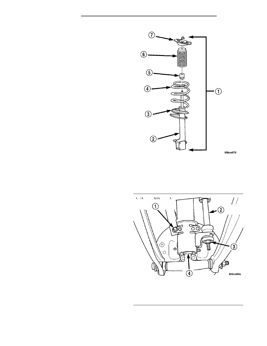
Fig. 13 Strut Assembly

1 - STRUT ASSEMBLY
2 - STRUT
3 - LOWER SPRING ISOLATOR
4 - COIL SPRING
5 - JOUNCE BUMPER
6 - DUST SHIELD
7 - UPPER MOUNT

Fig. 14 Rear of Strut Assembly

1 - BRAKE HOSE BRACKET SCREW
2 - STABILIZER BAR LINK
3 - NUT
4 - STRUT ASSEMBLY

2 - 42

REAR SUSPENSION

PL/SRT-4

STRUT ASSEMBLY (Continued)

(6) If the vehicle is equipped with rear disc brakes

(Fig. 16), perform the following:

• Remove the two guide pin bolts securing the

front disc brake caliper to the steering knuckle.

• Remove the disc brake caliper from the knuckle

and brake rotor.

• Hang the caliper out of the way using a wire

hanger or cord. Do not support the caliper by letting
it hang by the hydraulic hose.

CAUTION: The strut-to-knuckle attaching bolts are
serrated and must not be turned during removal.
Hold the bolts stationary in the steering knuckle
while removing the nuts, then tap the bolts out
using a pin punch.

(7) Remove the two nuts and bolts attaching the

strut to the rear knuckle (Fig. 1).

(8) Lower the vehicle just enough to access the

luggage compartment without letting the tires touch
the floor. Access to rear upper strut mount attaching
bolts is through the luggage compartment.

(9) Open the deck lid.
(10) If equipped, remove the carpet from the top of

the strut tower.

(11) Loosen, but do not completely remove the 3

nuts securing the strut assembly to the strut tower
(Fig. 17).

Grasp the strut assembly to keep it from moving,

then remove the 3 mounting nuts at the strut tower.

(12) Remove the strut assembly from the knuckle

by sliding it away from the knuckle, lowering it
between the two lateral arms, then tipping the top
outward and removing it out through the well open-
ing.

(13) For

disassembly

procedures

of

the

strut

assembly, (Refer to 2 - SUSPENSION/REAR/STRUT
- DISASSEMBLY).

DISASSEMBLY - STRUT ASSEMBLY (REAR)

The strut assembly must be removed from the

vehicle for it to be disassembled and assembled.
(Refer

to

2

-

SUSPENSION/REAR/STRUT

-

REMOVAL).

For the disassembly and assembly of the strut

assembly, use strut spring compressor, Pentastar Ser-

Fig. 15 Rear of Strut Assembly with ABS

1 - ABS WHEEL SPEED SENSOR BRACKET SCREW
2 - STABILIZER BAR LINK
3 - NUT
4 - STRUT ASSEMBLY

Fig. 16 Rear Disc Brakes

1 - DISC BRAKE CALIPER
2 - DISC BRAKE ADAPTER
3 - GUIDE PIN BOLTS
4 - HUB AND BEARING
5 - BRAKE ROTOR
6 - RETAINER CLIP
7 - DUST CAP
8 - NUT

Fig. 17 Mounting At Strut Tower

1 - UPPER MOUNT
2 - MOUNTING NUTS
3 - STRUT TOWER

PL/SRT-4

REAR SUSPENSION

2 - 43

STRUT ASSEMBLY (Continued)

vice Equipment (PSE) tool W-7200, or the equivalent,
to compress the coil spring. Follow the manufactur-
er’s instructions closely.

(1) If both struts are being serviced at the same

time, mark the coil spring and strut assembly accord-
ing to which side of the vehicle the strut was
removed from, and which strut the coil spring was
removed from.

(2) Position the strut assembly in the strut coil

spring

compressor

following

the

manufacturers

instructions. Set the lower, then upper hooks on the
coil spring (Fig. 18). Position the strut clevis bracket
straight inward toward the compressor. Place a
clamp on the lower end of the coil spring, so the strut
is held in place once the strut shaft nut is removed.

WARNING: DO NOT REMOVE THE STRUT SHAFT
NUT BEFORE THE COIL SPRING IS COMPRESSED.
THE COIL SPRING IS HELD UNDER PRESSURE
AND MUST BE COMPRESSED, REMOVING SPRING
TENSION FROM THE UPPER MOUNT AND PIVOT
BEARING, BEFORE THE SHAFT NUT IS REMOVED.

(3) Compress the coil spring until all coil spring

tension is removed from the upper mount.

(4) Once the spring is sufficiently compressed,

install Strut Nut Socket, Special Tool 6864, on the
strut shaft retaining nut (Fig. 19). Next, install a
socket on the hex on the end of the strut shaft. While
holding the strut shaft from turning, remove the nut
from the strut shaft.

(5) Remove the upper mount from the strut shaft

(Fig. 20).

(6) Remove the clamp from the bottom of the coil

spring and remove the strut out through the bottom
of the coil spring.

(7) Remove the dust shield, then the jounce

bumper from the strut shaft by pulling each straight
up (Fig. 20).

(8) Remove the lower spring isolator from the

lower spring seat located on the strut.

NOTE: If the coil spring needs to be serviced, pro-
ceed with the next step, otherwise, proceed with
step 10.

NOTE: Before removing the coil spring from the
compressor, make not of its position in the com-
pressor, for easy reassembly.

(9) Release the tension from the coil spring by

backing off the compressor drive completely. Push
back the compressor hooks and remove the coil
spring.

(10) Inspect the strut assembly components for the

following and replace as necessary:

• Inspect the strut for any condition of shaft bind-

ing over the full stroke of the shaft.

Fig. 18 Strut Assembly In Compressor

1 - UPPER HOOKS
2 - COIL SPRING
3 - CLEVIS BRACKET
4 - CLAMP
5 - LOWER HOOKS

Fig. 19 Shaft Nut Removal/Installation

1 - UPPER MOUNT
2 - FRONT HOOK

2 - 44

REAR SUSPENSION

PL/SRT-4

STRUT ASSEMBLY (Continued)

• Inspect the jounce bumper for cracks and signs

of deterioration.

• Check the upper mount for cracks and distortion

and its retaining studs for any sign of damage.

• Inspect the dust shield for rips and deteriora-

tion.

• Inspect the upper and lower spring isolators for

material deterioration and distortion.

• Inspect the coil spring for any sign of damage to

the coating.

ASSEMBLY - STRUT ASSEMBLY (REAR)

The strut assembly must be removed from the

vehicle for it to be disassembled and assembled.
(Refer

to

2

-

SUSPENSION/REAR/STRUT

-

REMOVAL).

For the disassembly and assembly of the strut

assembly, use strut spring compressor, Pentastar Ser-
vice Equipment (PSE) tool W-7200, or the equivalent,
to compress the coil spring. Follow the manufactur-
er’s instructions closely.

NOTE: If the coil spring has been removed from the
spring compressor, proceed with the next step, oth-
erwise, proceed with step 3.

(1) Place the coil spring in the compressor follow-

ing the manufacturers instructions. Before compress-
ing the spring, rotate the spring to the position
determined in the note prior to step 9 in disassembly.

(2) Slowly compress the coil spring until enough

room is available for strut assembly reassembly.

(3) Install the lower spring isolator on the lower

spring seat of the strut matching the step built into
the isolator with the step in the lower spring seat on
the strut (Fig. 20).

(4) Install the jounce bumper on the strut shaft.

The jounce bumper is to be installed with the pointed
end pointing downward toward the lower seat.

(5) Install the dust shield on the strut shaft (Fig.

20). The bottom of the dust shield will snap past the
retainer on top of the strut housing.

(6) Install the strut through the bottom of the coil

spring until the lower spring seat contacts the lower
end of the coil spring. Rotate the strut until the end
of the coil spring fits against the step in the lower
spring seat (Fig. 18). If done correctly, the clevis on
the bottom of the strut should face toward the com-
pressor.

(7) Install the clamp on the lower end of the coil

spring and strut, so the strut is held in place with
the coil spring.

NOTE: Before installing the upper mount, check to
make sure the correct side mount is being installed.
Left and right upper mounts are different. A left
mount will be marked with the letter “L” while a
right mount will be marked with the letter “R” (Fig.
21).

(8) Install the upper mount over the strut shaft

and onto the top of the upper spring. Near the center
on the top of the mount is the word “OUT” and an
arrow (Fig. 21). Point the arrow on the mount in the

Fig. 20 Strut Assembly Components

1 - STRUT ASSEMBLY
2 - STRUT
3 - LOWER SPRING ISOLATOR
4 - COIL SPRING
5 - JOUNCE BUMPER
6 - DUST SHIELD
7 - UPPER MOUNT

Fig. 21 Upper Mount Markings

1 - SIDE INDICATING LETTER
2 - DIRECTIONAL INDICATOR
3 - UPPER MOUNT

PL/SRT-4

REAR SUSPENSION

2 - 45

STRUT ASSEMBLY (Continued)


Content   ..  18  19  20  21   ..