Dodge Neon / Neon SRT-4. Manual - part 16


  Index      Dodge     Dodge Neon / Neon SRT-4 - service repair manual 2005 year


Search            


Content   ..  14  15  16  17   ..


Dodge Neon / Neon SRT-4. Manual - part 16


(1) If removed, install the stabilizer bar cushions

on the stabilizer bar utilizing the slit in each cush-
ion. Position the cushions at each end of the bar’s
straight beam, just before it begins to curve.

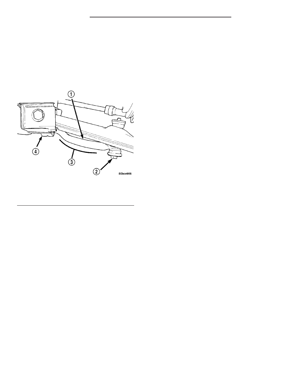
NOTE: Before installing the stabilizer bar, make
sure the bar is not upside-down. The stabilizer bar
must be installed with the curve on the outboard
ends of the bar facing downward to clear the con-
trol arms once fully installed (Fig. 53).

(2) First, place the stabilizer bar in position on the

front suspension crossmember. The slits in each
cushion must point toward the front of the vehicle
and sit directly on top of the raised beads formed
into the stamping on the crossmember. Next, install
the cushion retainers, matching the raised beads
formed into the cushion retainers to the grooves
formed into the cushions. Install the cushion retainer
bolts, but do not completely tighten them at this
time.

(3) Install both stabilizer bar links back on vehicle

(Fig. 52). Start each stabilizer bar link bolt with
bushing from the bottom, through the stabilizer bar,
inner link bushings, lower control arm, and into the
upper retainer/nut and bushing (Fig. 1). Do not fully
tighten the link assemblies at this time.

(4) Lower the vehicle.

NOTE: It may be necessary to put the vehicle on a
platform hoist or alignment rack to gain access to
the stabilizer bar mounting bolts with the vehicle at
curb height.

(5) Tighten each stabilizer bar link by holding the

upper retainer/nut with a wrench and turning the

link bolt. Tighten each link bolt to a torque of 31
N·m (275 in. lbs.).

(6) Tighten the stabilizer bar cushion retainer

bolts to a torque of 28 N·m (250 in. lbs.).

STRUT ASSEMBLY

DESCRIPTION - STRUT ASSEMBLY (FRONT)

A Macpherson type design strut assembly is used

in place of the front suspension upper control arm
and upper ball joint (Fig. 1). The bottom of the strut
mounts directly to the steering knuckle using 2
attaching bolts and nuts going through the strut cle-
vis bracket and steering knuckle. The top of the strut
mounts directly to the strut tower of the vehicle
using the three threaded studs on the strut assem-
blies upper mount. During steering maneuvers, the
strut assembly (through a pivot bearing in the upper
strut mount) and steering knuckle (through the lower
ball joint) turn as an assembly.

The strut assembly includes the following compo-

nents:

• Strut shaft retaining nut

• Upper mount (rubber isolated)

• Upper spring seat and bearing

• Dust shield

• Jounce bumper

• Coil spring

• Lower spring isolator

• Strut (damper)
Each component is serviced by removing the strut

assembly from the vehicle and disassembling it.

The strut and front suspension of the vehicle is

supported by coil springs positioned around the
upper half of each strut. The springs are contained
between the upper and the lower seats of the strut
assembly.

Coil springs are rated separately for each corner or

side of the vehicle depending on optional equipment
and type of vehicle service. During service procedures
of the strut assembly, if both springs are removed,
mark the springs to ensure installation in its original
position.

NOTE: If a coil spring requires replacement, be sure
that it is replaced with a spring meeting the correct
load rating for the vehicle and its specific options.

OPERATION - STRUT ASSEMBLY (FRONT)

The strut assembly cushions the ride of the vehicle,

controlling vibration, jounce and rebound of the sus-
pension.

The coil spring controls ride quality and maintains

proper ride height.

Fig. 53 Downward Curve

1 - STABILIZER BAR
2 - LINK
3 - DOWNWARD CURVE
4 - CUSHION RETAINER

2 - 26

FRONT SUSPENSION

PL/SRT-4

STABILIZER BAR (Continued)

The spring isolators isolate the coil spring at the

top and bottom from coming into metal-to-metal con-
tact with the upper mounting seat and the strut.

The jounce bumper limits suspension travel and

metal-to-metal contact under full jounce condition.

The strut dampens jounce and rebound motions of

the coil spring and suspension.

DIAGNOSIS AND TESTING - STRUT ASSEMBLY
(FRONT)

Inspect the strut assembly for the following condi-

tions (Fig. 54):

• Inspect for a damaged or broken coil spring.

• Inspect for a torn or damaged strut assembly

dust shield.

• Lift the dust shield and inspect the strut assem-

bly for evidence of fluid running from the upper end
of the strut fluid reservoir. (Actual leakage will be a
stream of fluid running down the side and dripping
off lower end of unit). A slight amount of seepage
between the strut shaft and strut shaft seal is not
unusual and does not affect performance of the strut
assembly.

• Lift the dust shield and inspect the jounce

bumper for signs of damage or deterioration (non-
ACR vehicles only).

• Inspect the clearance between the shock tower

and the coil spring. Make sure no fasteners are pro-
truding through the shock tower possibly contacting
the coil spring and strut. Because of the minimum
clearance in this area (Fig. 55), installation of metal
fasteners could damage the coil spring coating and
lead to a corrosion failure of the spring.

CAUTION: At no time when servicing a vehicle can
a sheet metal screw, bolt or other metal fastener be
installed into the shock tower to take the place of
an original plastic clip. Also, do not drill holes into
the front shock tower for the installation of any
metal fasteners into the shock tower area indicated
(Fig. 55).

REMOVAL - STRUT ASSEMBLY (FRONT)

NOTE: Before proceeding with this procedure,
(Refer to 2 - SUSPENSION/FRONT - WARNING).

(1) Raise the vehicle. (Refer to LUBRICATION &

MAINTENANCE/HOISTING - STANDARD PROCE-
DURE).

(2) Remove tire and wheel assembly from location

on front of vehicle requiring strut removal. (Refer to
22 - TIRES/WHEELS - REMOVAL)

(3) If both strut assemblies are to be removed,

mark the strut assemblies right or left according to
which side of the vehicle they were removed from.

Fig. 54 Strut Assembly

1 - NUT
2 - STRUT ASSEMBLY
3 - STRUT
4 - LOWER SPRING ISOLATOR
5 - COIL SPRING
6 - JOUNCE BUMPER
7 - DUST SHIELD
8 - SPRING SEAT AND BEARING (WITH SPRING ISOLATOR)
9 - UPPER MOUNT

Fig. 55 Shock Tower Area (Typical)

1 - SHOCK TOWER
2 - COIL SPRING
3 - NO SHEET METAL SCREWS, BOLTS, OR ANY OTHER METAL
FASTENERS ARE TO BE INSTALLED INTO SHOCK TOWER IN
THIS AREA. ALSO, NO HOLES ARE TO BE DRILLED INTO
SHOCK TOWER IN THIS SAME AREA.

PL/SRT-4

FRONT SUSPENSION

2 - 27

STRUT ASSEMBLY (Continued)

(4) Remove the screw securing the ground strap to

the rear of the strut (Fig. 56).

(5) If the vehicle is equipped with Antilock brakes

(ABS), remove the screw securing the ABS wheel
speed sensor to the rear of the strut (Fig. 56).

CAUTION: The strut assembly-to-steering knuckle
attaching bolts are serrated and must not be turned
during removal. Hold the bolts stationary in the
steering knuckle while removing the nuts, then tap
the bolts out using a pin punch.

(6) Remove the two bolts attaching the strut to the

steering knuckle (Fig. 1).

(7) Lower the vehicle just enough to open the

hood, but without letting the tires touch the floor.

(8) Remove the three nuts attaching the upper

mount of the strut assembly to the vehicle’s strut
tower (Fig. 57).

(9) Remove the strut assembly from the vehicle.
(10) For disassembly procedures, (Refer to 2 -

SUSPENSION/FRONT/STRUT - DISASSEMBLY).

DISASSEMBLY - STRUT ASSEMBLY (FRONT)

The Strut assembly must be removed from the

vehicle for it to be disassembled and assembled.
(Refer

to

2

-

SUSPENSION/FRONT/STRUT

-

REMOVAL).

For the disassembly and assembly of the strut

assembly, use strut spring compressor, Pentastar Ser-
vice Equipment (PSE) tool W-7200, or the equivalent,
to compress the coil spring. Follow the manufactur-
er’s instructions closely.

(1) If both struts are being serviced at the same

time, mark the coil spring and strut assembly accord-
ing to which side of the vehicle the strut was
removed from, and which strut the coil spring was
removed from.

(2) Position the strut assembly in the strut coil

spring

compressor

following

the

manufacturers

instructions. Set the lower hooks (Fig. 58), then set
the upper hooks (Fig. 59). Position the strut clevis
bracket straight outward away from the compressor.
Place a clamp on the lower end of the coil spring, so
the strut is held in place once the strut shaft nut is
removed (Fig. 58).

WARNING: DO NOT REMOVE THE STRUT SHAFT
NUT BEFORE THE COIL SPRING IS COMPRESSED.
THE COIL SPRING IS HELD UNDER PRESSURE
AND MUST BE COMPRESSED, REMOVING SPRING
TENSION FROM THE UPPER MOUNT AND PIVOT
BEARING, BEFORE THE SHAFT NUT IS REMOVED.

(3) Compress the coil spring until all coil spring

tension is removed from the upper mount.

(4) Once the spring is sufficiently compressed,

install Strut Nut Socket, Special Tool 6864, on the
strut shaft retaining nut (Fig. 60). Next, install a
socket on the hex on the end of the strut shaft. While
holding the strut shaft from turning, remove the nut
from the strut shaft.

(5) Remove the upper mount from the strut shaft

(Fig. 61).

(6) Remove the upper spring seat and bearing,

along with the upper spring isolator as an assembly
from the top of the coil spring by pulling them
straight up (Fig. 61). The upper spring isolator can
be separated from the spring seat and bearing once
removed from vehicle.

Fig. 56 Ground Strap And ABS Sensor Bracket

1 - ABS WHEEL SPEED SENSOR ROUTING BRACKET (IF
EQUIPPED)
2 - GROUND STRAP
3 - GROUND STRAP SCREW
4 - ABS SENSOR BRACKET SCREW (IF EQUIPPED)

Fig. 57 Upper Mounting Nuts

1 - STRUT TOWER
2 - MOUNTING NUTS

2 - 28

FRONT SUSPENSION

PL/SRT-4

STRUT ASSEMBLY (Continued)

(7) Remove the dust shield, then the jounce

bumper from the strut shaft by pulling each straight
up (Fig. 61).

(8) Remove the clamp from the bottom of the coil

spring and remove the strut out through the bottom
of the coil spring.

(9) Remove the lower spring isolator from the

lower spring seat on the strut.

NOTE: If the coil spring needs to be serviced, pro-
ceed with the next step, otherwise, proceed with
step 11.

(10) Release the tension from the coil spring by

backing off the compressor drive completely. Push
back the compressor hooks and remove the coil
spring.

(11) Inspect the strut assembly components for the

following and replace as necessary:

• Inspect the strut for any condition of shaft bind-

ing over the full stroke of the shaft.

• Inspect the jounce bumper for cracks and signs

of deterioration (non-ACR vehicles only).

• Check the upper mount for cracks and distortion

and its retaining studs for any sign of damage.

• Check the upper spring seat and bearing for

cracks and distortion.

• Check for binding of the upper spring seat and

bearing pivot bearing.

Fig. 58 Strut Assembly In Compressor (Lower)

1 - LOWER HOOKS
2 - CLAMP
3 - STRUT ASSEMBLY
4 - CLEVIS BRACKET
5 - SPRING COMPRESSOR

Fig. 59 Strut Assembly In Compressor (Upper)

1 - NOTCH IN UPPER SEAT
2 - UPPER MOUNT
3 - UPPER HOOKS
4 - CLEVIS BRACKET

Fig. 60 Shaft Nut Removal/Installation

1 - SPRING COMPRESSOR
2 - SPECIAL TOOL 6864
3 - UPPER MOUNT

PL/SRT-4

FRONT SUSPENSION

2 - 29

STRUT ASSEMBLY (Continued)


Content   ..  14  15  16  17   ..