Dodge Neon / Neon SRT-4. Manual - part 14


  Index      Dodge     Dodge Neon / Neon SRT-4 - service repair manual 2005 year


Search            


Content   ..  12  13  14  15   ..


Dodge Neon / Neon SRT-4. Manual - part 14


(14) Set the front toe on the vehicle to required

specification. (Refer to 2 - SUSPENSION/WHEEL
ALIGNMENT - STANDARD PROCEDURE)

LOWER BALL JOINT

DIAGNOSIS AND TESTING - BALL JOINT

With the weight of the vehicle resting on the road

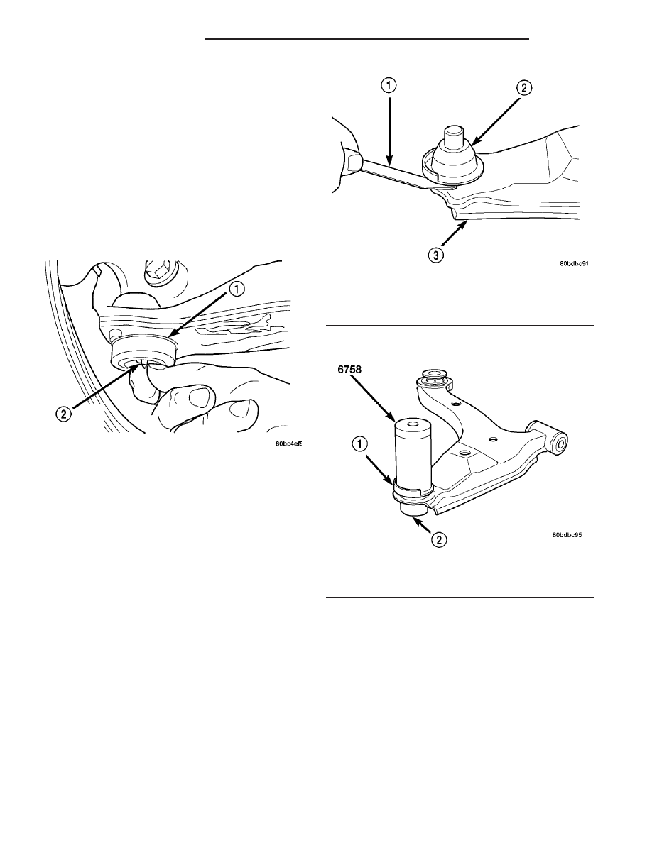
wheels, grasp the headless grease fitting as shown
(Fig. 34). With no mechanical assistance or added
force, attempt to move the grease fitting. If the ball
joint is worn, the grease fitting will move. If move-
ment is noted, replace the ball joint.

CAUTION: No attempt should be made to service
the headless grease fitting on the ball joint. It has
been purposely snapped off by the manufacturer to
avoid over-greasing.

LOWER BALL JOINT SEAL
BOOT

REMOVAL

(1) Remove steering knuckle from vehicle. (Refer

to

2

-

SUSPENSION/FRONT/KNUCKLE

-

REMOVAL)

(2) Using a screwdriver or other suitable tool, pry

seal boot off of ball joint (Fig. 35).

INSTALLATION

(1) Wipe off used grease around ball joint stem.

CAUTION: When installing the sealing boot on the
ball joint, position the upward lip on the seal boot
outside perimeter outward, away from the control

arm once installed (Fig. 36). It is there to help shield
heat from the sealing boot.

(2) Place NEW ball joint seal boot over ball joint

stem. Upward lip located on outside perimeter of seal
boot must point outward, away from control arm
once installed (Fig. 36).

(3) By hand, start sealing boot over sides of the

ball joint.

(4) Position Installer, Special Tool 6758, over seal-

ing boot outer diameter as shown (Fig. 36). By hand,
apply pressure to top of Installer until seal boot is
pressed squarely down against top surface of lower
control arm.

(5) Remove tool.
(6) Remove headless grease fitting on ball joint

and replace it with standard zirc-type grease fitting.
Do not discard headless grease fitting.

Fig. 34 Checking Ball Joint Wear

1 - BALL JOINT
2 - HEADLESS GREASE FITTING

Fig. 35 Seal Boot Removal

1 - TOOL
2 - SEAL BOOT
3 - LOWER CONTROL ARM

Fig. 36 Seal Boot Installation

1 - SEAL BOOT UPWARD LIP
2 - BALL JOINT

2 - 18

FRONT SUSPENSION

PL/SRT-4

KNUCKLE - SRT-4 (Continued)

CAUTION: It is important to lubricate the ball joint
before installation of steering knuckle to allow
proper venting when the seal is filled. If the ball
joint is lubricated after installation to knuckle, dam-
age to the seal can occur.

(7) Using a hand operated pump grease gun, fill

the ball joint seal boot with Mopar

t Multi-Mileage

Lube or equivalent until grease pushes out past ball
joint stem. Wipe off overfill.

(8) Remove standard zirc-type grease fitting and

reinstall headless grease fitting on ball joint to pre-
vent future lubricating. See above caution.

(9) Install steering knuckle. (Refer to 2 - SUSPEN-

SION/FRONT/KNUCKLE - INSTALLATION)

LOWER CONTROL ARM

DESCRIPTION

There is one lower control arm on each side of the

vehicle. Each lower control arm is a stamped steel
unit using rubber isolated pivot bushings to isolate it
from the front suspension crossmember and frame of
the vehicle (Fig. 1). The rear bushing can be serviced
separately.

The front of the lower control arm is bolted to the

front crossmember using a bolt through the center of
the rubber pivot bushing. The rear of the lower con-
trol arm is mounted to both the front crossmember
and the frame rail of the vehicle using a thru-bolt.
The thru-bolt goes through both the crossmember
and rear lower control arm bushing, threading
directly into the frame rail of the vehicle.

The left and right lower control arms are intercon-

nected through a linked rubber isolated stabilizer
bar.

The outboard end of each lower control arm con-

nects to the steering knuckle using a ball joint.

The lower control arm connects to the steering

knuckle through a ball joint mounted at the outboard
end of the arm (Fig. 1). The ball joint is pressed into
the lower control arm and has a non-tapered stud
with a notch for steering knuckle pinch bolt clear-
ance. The ball joint stud is clamped and locked to the
steering knuckle lower leg using a pinch bolt.

The ball joint is lubricated for life during the man-

ufacturing process. Once lubricated for life, the
grease fitting head is snapped off by the manufac-
turer. This is done to eliminate the possibility of
lubrication later in the ball joints life thus damaging
the non-vented ball joint seal boot.

The ball joint used on this vehicle is replaceable

and, if found defective, can be serviced as a separate
component of the lower control arm.

DIAGNOSIS AND TESTING - LOWER CONTROL
ARM

Inspect the lower control arm for signs of damage

from contact with the ground or road debris. If the
lower control arm shows any sign of damage, look for
distortion. Do not attempt to repair or straighten a
broken or bent lower control arm. If damaged, the
lower control arm stamping is serviced only as a
complete component.

The serviceable components of the lower control

arm are: the ball joint, the ball joint grease seal and
the lower control arm rear isolator bushing. The
front isolator bushing is not replaceable. If the front
isolator bushing needs to be replaced, the entire
lower control arm must be replaced.

Inspect both lower control arm isolator bushings

for severe deterioration and replace lower control
arm or rear bushing as required. Inspect the ball
joint per the inspection procedure in this section of
the service manual and replace as required. (Refer to
2 - SUSPENSION/FRONT/LOWER BALL JOINT -
DIAGNOSIS AND TESTING).

REMOVAL - LOWER CONTROL ARM

NOTE: Before proceeding with this procedure,
(Refer to 2 - SUSPENSION/FRONT - WARNING).

(1) Raise the vehicle. (Refer to LUBRICATION &

MAINTENANCE/HOISTING - STANDARD PROCE-
DURE).

(2) Remove the front tire and wheel assembly

(Refer to 22 - TIRES/WHEELS - REMOVAL).

(3) Remove both stabilizer bar links from the vehi-

cle (Fig. 37). Remove each link by holding the upper
retainer/nut with a wrench and turning the link bolt.

(4) Rotate the forward ends of the stabilizer bar

downward. It may be necessary to loosen the stabi-
lizer bar cushion retainer bolts a little to ease any
turning resistance.

(5) Remove the nut and pinch bolt clamping the

ball joint stud to the steering knuckle (Fig. 38).

CAUTION: After removing the steering knuckle from
the ball joint stud, do not pull outward on the
knuckle. Pulling the steering knuckle outward at
this point can separate the inner C/V joint on the
driveshaft.

NOTE: Use caution when separating the ball joint
stud from the steering knuckle, so the ball joint seal
does not get cut.

(6) Separate the ball joint stud from the steering

knuckle by prying down on lower control arm and up

PL/SRT-4

FRONT SUSPENSION

2 - 19

LOWER BALL JOINT SEAL BOOT (Continued)

against the ball joint boss on the steering knuckle
(Fig. 39).

(7) If the right lower control arm is being serviced,

perform the following:

(a) Remove the drive-belt splash shield fasten-

ers. Remove the shield.

(b) Remove the pencil strut from the right front

corner of the crossmember and body of the vehicle
(Fig. 40). Remove the washer behind the strut from
the torque strut bolt.

(c) Remove the bolts mounting the engine torque

strut in place (Fig. 40), then remove the engine
torque strut from the vehicle.

(8) Remove the front pivot bolt attaching the lower

control arm to the front suspension crossmember
(Fig. 41). Remove the rear pivot bolt attaching the
lower control arm to the front suspension crossmem-
ber and frame rail. Remove the lower control arm
from the crossmember.

Fig. 37 Stabilizer Bar Links

1 - STABILIZER BAR CUSHION RETAINERS
2 - CUSHIONS
3 - FRONT STABILIZER BAR
4 - STABILIZER BAR LINKS

Fig. 38 Ball Joint Bolt And Nut

1 - NUT
2 - BOLT
3 - BALL JOINT

Fig. 39 Separate Ball Joint from Knuckle

1 - STEERING KNUCKLE
2 - PRY BAR
3 - LOWER CONTROL ARM
4 - BALL JOINT STUD

Fig. 40 Strut Mounting

1 - NUT
2 - PENCIL STRUT
3 - NUT
4 - FLAT WASHER
5 - LOWER TORQUE STRUT

2 - 20

FRONT SUSPENSION

PL/SRT-4

LOWER CONTROL ARM (Continued)

DISASSEMBLY

DISASSEMBLY - LOWER CONTROL ARM (BALL
JOINT)

NOTE: The removal and installation of the lower
ball joint from the lower control arm is to be done
with the lower control arm removed from the vehi-
cle. (Refer to 2 - SUSPENSION/FRONT/LOWER
CONTROL ARM - REMOVAL).

(1) Using a screwdriver or other suitable tool, pry

the seal boot off of the ball joint (Fig. 42).

(2) Position the Receiver, Special Tool 6908-2, on a

hydraulic press to support the lower control arm
(Fig. 43). Place the control arm on top of Tool 6908-2
so that the bottom of the ball joint sets into the
Receiver cup.

(3) Place the larger end of the Adapter, Special

Tool 6804, on top of the ball joint as shown (Fig. 43).

(4) Using the hydraulic press, press the ball joint

completely out of the lower control arm, into the
receiver.

(5) Remove the tools, ball joint and arm from the

hydraulic press.

DISASSEMBLY - LOWER CONTROL ARM
(REAR ISOLATOR BUSHING)

NOTE: The removal and installation of the rear iso-
lator bushing from the lower control arm is only to
be done with the lower control arm removed from
the vehicle (Refer to 2 - SUSPENSION/FRONT/
LOWER CONTROL ARM - REMOVAL). The front iso-
lator bushing is not serviceable.

NOTE: To maintain better control when removing
the rear isolator bushing, it works best to mount
Ball Joint Press, Special Tool C-4212F, in a vise.

(1) Install the Receiver Cup, Special Tool 9356-4,

into the cup of the Ball Joint Press, Special Tool
C-4212F, and tighten the set screw (Fig. 45).

(2) Install the Remover, Special Tool 9356-2, on the

tip of the Ball Joint Press screw-drive.

(3) Install the Reaction Plate, Special Tool 9356-3,

over the end of the control arm so that the arrows on
the Reaction Plate point toward the bushing flange
on the bottom of the arm as shown (Fig. 44).

Fig. 41 Lower Control Arm Attaching Bolts

1 - LOWER CONTROL ARM
2 - FRONT BOLT
3 - CROSSMEMBER
4 - REAR BOLT

Fig. 42 Seal Boot Removal

1 - TOOL
2 - SEAL BOOT
3 - LOWER CONTROL ARM

Fig. 43 Ball Joint Removal

1 - PRESS
2 - BALL JOINT

PL/SRT-4

FRONT SUSPENSION

2 - 21

LOWER CONTROL ARM (Continued)


Content   ..  12  13  14  15   ..