Dodge Caliber. Manual - part 977


  Index      Dodge     Dodge Caliber - service repair manual 2007 year


Search            


Content   ..  975  976  977  978   ..


Dodge Caliber. Manual - part 977


4.

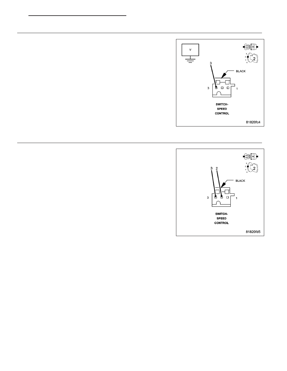
(V937) S/C SWITCH GROUND CIRCUIT SHORTED TO VOLTAGE

Turn the ignition off.

Remove the Main Relay.

Connect a jumper wire between cavity B7 and cavity B9 of the Main
Relay connector.

Turn the ignition on.

Measure the voltage of the (V937) S/C Switch Ground circuit.

Is there any voltage present?

Yes

>> Repair the (V937) S/C Switch Ground circuit for a short to

voltage.

Perform the ECM Verification Test Ver.1. (Refer to 9 -
ENGINE - DIAGNOSIS AND TESTING)

No

>> Go to 5

5.

S/C SWITCH

Turn the ignition off.

Connect the Engine Control Module (ECM) harness connector.

Turn the ignition on.

With the scan tool, monitor the S/C Switch Voltage.

While monitoring the scan tool, connect a jumper wire between the
(V71) S/C Switch 1 Signal circuit and the (V937) S/C Switch Ground
circuit in the S/C Switch harness connector.

Does the scan tool display below 0.1 volt with the jumper wire
in place?

Yes

>> Replace the Speed Control Switches in accordance with the

Service Information.

Perform the ECM Verification Test Ver.1. (Refer to 9 -
ENGINE - DIAGNOSIS AND TESTING)

No

>> Go to 9

PM

ENGINE ELECTRICAL DIAGNOSTICS - DIESEL

9 - 1195

6.

(V71) S/C SWITCH 1 SIGNAL CIRCUIT OPEN OR HIGH RESISTANCE

Turn the ignition off.

Disconnect the Engine Control Module (ECM) harness connector.

Measure the resistance of the (V71) S/C Switch 1 Signal circuit
between the Speed Control Switch harness connector and the Engine
Control Module (ECM) harness connector.

Is the resistance below 10.0 ohms?

Yes

>> Go To 7

No

>> Repair the (V71) S/C Switch 1 Signal circuit for an open cir-

cuit or high resistance.

Perform the ECM Verification Test Ver.1. (Refer to 9 -
ENGINE - DIAGNOSIS AND TESTING)

7.

(V71) S/C SWITCH 1 SIGNAL CIRCUIT SHORTED TO GROUND

Measure the resistance between ground and the (V71) S/C Switch 1
Signal circuit.

Is the resistance above 1000 ohms?

Yes

>> Go to 9

No

>> Repair the (V71) S/C Switch 1 Signal circuit for a short to

ground.

Perform the ECM Verification Test Ver.1. (Refer to 9 -
ENGINE - DIAGNOSIS AND TESTING)

9 - 1196

ENGINE ELECTRICAL DIAGNOSTICS - DIESEL

PM

8.

(V71) S/C SWITCH 1 SIGNAL CIRCUIT SHORTED TO VOLTAGE

Turn the ignition off.

Disconnect the Engine Control Module (ECM) harness connector.

Remove the Main Relay.

Connect a jumper wire between cavity B7 and cavity B9 of the Main
Relay connector.

Turn the ignition on.

Measure the voltage of the (V71) S/C Switch 1 Signal circuit.

Is there any voltage present?

Yes

>> Repair the (V71) S/C Switch 1 Signal circuit for a short to

voltage.

Perform the ECM Verification Test Ver.1. (Refer to 9 -
ENGINE - DIAGNOSIS AND TESTING)

No

>> Go to 9

9.

ENGINE CONTROL MODULE (ECM)

Using the wiring diagram/schematic as a guide, inspect the wiring and connectors between the Speed Control
Switch and the Engine Control Module (ECM).

Look for any chafed, pierced, pinched, or partially broken wires.

Look for broken, bent, pushed out or corroded terminals.

Refer to any Technical Service Bulletins that may apply.

Were any problems found?

Yes

>> Repair as necessary.

Perform the ECM Verification Test Ver.1. (Refer to 9 - ENGINE - DIAGNOSIS AND TESTING)

No

>> Replace the Engine Control Module (ECM) in accordance with the Service Information.

Perform the ECM Verification Test Ver.1. (Refer to 9 - ENGINE - DIAGNOSIS AND TESTING)

PM

ENGINE ELECTRICAL DIAGNOSTICS - DIESEL

9 - 1197

P0585-SPEED CONTROL SWITCH 1 2 CORRELATION

For a complete wiring diagram Refer to Section 8W

9 - 1198

ENGINE ELECTRICAL DIAGNOSTICS - DIESEL

PM


Content   ..  975  976  977  978   ..