Dodge Caliber. Manual - part 920


  Index      Dodge     Dodge Caliber - service repair manual 2007 year


Search            


Content   ..  918  919  920  921   ..


Dodge Caliber. Manual - part 920


When Monitored:
With the ignition on.

Set Condition:
The Ambient Air Temperature Sensor signal is above 5.0 volts.

Possible Causes

(G31) AMBIENT AIR TEMP SENSOR SIGNAL CIRCUIT SHORTED TO VOLTAGE

(G931) AMBIENT AIR TEMP SENSOR GROUND CIRCUIT OPEN

(G31) AMBIENT AIR TEMP SENSOR SIGNAL CIRCUIT OPEN

AMBIENT AIR TEMPERATURE SENSOR

TOTALLY INTEGRATED POWER MODULE

Diagnostic Test

1.

CHECK FOR ACTIVE DTC

NOTE: If the ECM detects and stores a DTC, the ECM also stores the engine/vehicle operating conditions
under which the DTC was set. Some of these conditions are displayed on the scan tool at the same time the
DTC is displayed.

NOTE: Before erasing stored DTCs, record these conditions. Attempting to duplicate these conditions may
assist when checking for an active DTC.
Turn the ignition on.

With the scan tool, erase TIPM DTCs.

Turn the ignition off for 10 seconds.

Turn the ignition on.

Monitor the scan tool for TIPM DTCs.

Did this DTC set again?

Yes

>> Go To 2

No

>> Refer to the *CHECKING FOR AN INTERMITTENT DTC Diagnostic Procedure. (Refer to 9 - ENGINE -

DIAGNOSIS AND TESTING)

2.

(G31) AMBIENT AIR TEMP SENSOR SIGNAL CIRCUIT SHORTED TO VOLTAGE

Turn the ignition off.

Disconnect the Ambient Air Temperature Sensor harness connector.

Disconnect the TIPM C4 harness connector.

Remove the Main Relay.

Connect a jumper wire between cavity B7 and cavity B9 of the Main
Relay connector.

Turn the ignition on.

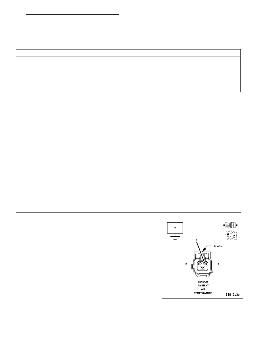
Measure the voltage on the (G31) Ambient Air Temperature Sensor Sig-
nal circuit.

NOTE: Remove the jumper wire.

Is the voltage below 1.0 volt?

Yes

>> Go To 3

No

>> Repair the (G31) Ambient Air Temperature Sensor Signal

circuit for a short to voltage.

Perform the ECM Verification Test Ver. 1 (Refer to 9 -
ENGINE - DIAGNOSIS AND TESTING).

PM

ENGINE ELECTRICAL DIAGNOSTICS - DIESEL

9 - 967

3.

(G31) AMBIENT AIR TEMP SENSOR SIGNAL CIRCUIT OPEN

Turn the ignition off.

Measure the resistance of the (G31) Ambient Air Temperature Sensor
Signal circuit between TIPM C4 harness connector and the Ambient Air
Temperature Sensor harness connector.

Is the resistance below 10.0 ohms?

Yes

>> Go To 4

No

>> Repair the (G31) Ambient Air Temperature Sensor Signal

circuit for an open.

Perform the ECM Verification Test Ver. 1 (Refer to 9 -
ENGINE - DIAGNOSIS AND TESTING).

4.

AMBIENT AIR TEMPERATURE SENSOR

Connect a jumper wire between the (G31) Ambient Temperature Sensor
Signal and the (G931) Sensor Ground circuit in the Ambient Tempera-
ture Sensor harness connector.

Turn the ignition on.

Monitor the scan tool for TIPM DTCs.

Does the scan tool display P0070 AMB TEMP. SENSOR CIR-
CUIT SIGNAL VOLTAGE TOO LOW?

Yes

>> Replace the Ambient Air Temperature Sensor.

Perform the ECM Verification Test Ver. 1 (Refer to 9 - ENGINE - DIAGNOSIS AND TESTING).

No

>> Go To 5

5.

(G931) AMBIENT AIR TEMP SENSOR GROUND CIRCUIT OPEN

Turn the ignition off.

Measure the resistance of the (G931) Ambient Air Temperature Sensor
Ground circuit between the TIPM C4 harness connector and the Ambi-
ent Air Temperature Sensor harness connector.

Is the resistance below 10.0 ohms?

Yes

>> Replace and program the TIPM in accordance with the Ser-

vice Information.

Perform the ECM Verification Test Ver. 1 (Refer to 9 -
ENGINE - DIAGNOSIS AND TESTING).

No

>> Repair the (G931) Ambient Air Temperature Sensor Ground

circuit for an open.

Perform the ECM Verification Test Ver. 1 (Refer to 9 -
ENGINE - DIAGNOSIS AND TESTING).

9 - 968

ENGINE ELECTRICAL DIAGNOSTICS - DIESEL

PM

P0101-MASS AIR FLOW SENSOR PERFORMANCE

For a complete wiring diagram Refer to Section 8W

PM

ENGINE ELECTRICAL DIAGNOSTICS - DIESEL

9 - 969

When Monitored:
With the ignition on.

Set Condition:
The ECM detects that the (K157) Mass Air Flow Sensor Signal circuit is not within a valid range.

Possible Causes

INTERMITTENT DTC

(K157) MASS AIR FLOW SENSOR SIGNAL CIRCUIT SHORTED TO VOLTAGE

(K957) MASS AIR FLOW SENSOR GROUND CIRCUIT SHORTED TO VOLTAGE

(K344) FUSED MAIN RELAY OUTPUT CIRCUIT OPEN OR HIGH RESISTANCE

(K157) MASS AIR FLOW SENSOR SIGNAL CIRCUIT OPEN OR HIGH RESISTANCE

(K957) MASS AIR FLOW SENSOR GROUND CIRCUIT OPEN OR HIGH RESISTANCE

(K157) MASS AIR FLOW SENSOR SIGNAL CIRCUIT SHORTED TO GROUND

(K157) MASS AIR FLOW SENSOR SIGNAL CIRCUIT SHORTED TO THE (K957) MASS AIR FLOW SENSOR
GROUND CIRCUIT

MASS AIR FLOW SENSOR

ENGINE CONTROL MODULE (ECM)

Always perform the Pre-Diagnostic Troubleshooting procedure before proceeding. (Refer to 9 - ENGINE -
DIAGNOSIS AND TESTING)

Diagnostic Test

1.

DTC IS ACTIVE

Ignition on, engine not running.

With the scan tool, Clear DTCs in the Engine Control Module (ECM).

Start the engine and allow it to reach normal operating temperature.

With the scan tool, select View DTCs.

Is the status Active for this DTC?

Yes

>> Go To 2

No

>> Refer to the *CHECKING FOR AN INTERMITTENT DTC Diagnostic Procedure. (Refer to 9 - ENGINE -

DIAGNOSIS AND TESTING)

2.

(K157) MASS AIR FLOW SENSOR SIGNAL CIRCUIT SHORTED TO VOLTAGE

Turn the ignition off.

Disconnect the Mass Air Flow Sensor harness connector.

Turn the ignition on.

Measure the voltage of the (K157) Mass Air Flow Sensor Signal circuit
in the Mass Air Flow Sensor harness connector.

Is there any voltage present?

Yes

>> Repair the (K157) Mass Air Flow Sensor Signal circuit for a

short to voltage.

Perform the ECM Verification Test Ver. 1. (Refer to 9 -
ENGINE - DIAGNOSIS AND TESTING)

No

>> Go to 3

9 - 970

ENGINE ELECTRICAL DIAGNOSTICS - DIESEL

PM


Content   ..  918  919  920  921   ..