Dodge Caliber. Manual - part 841
9.
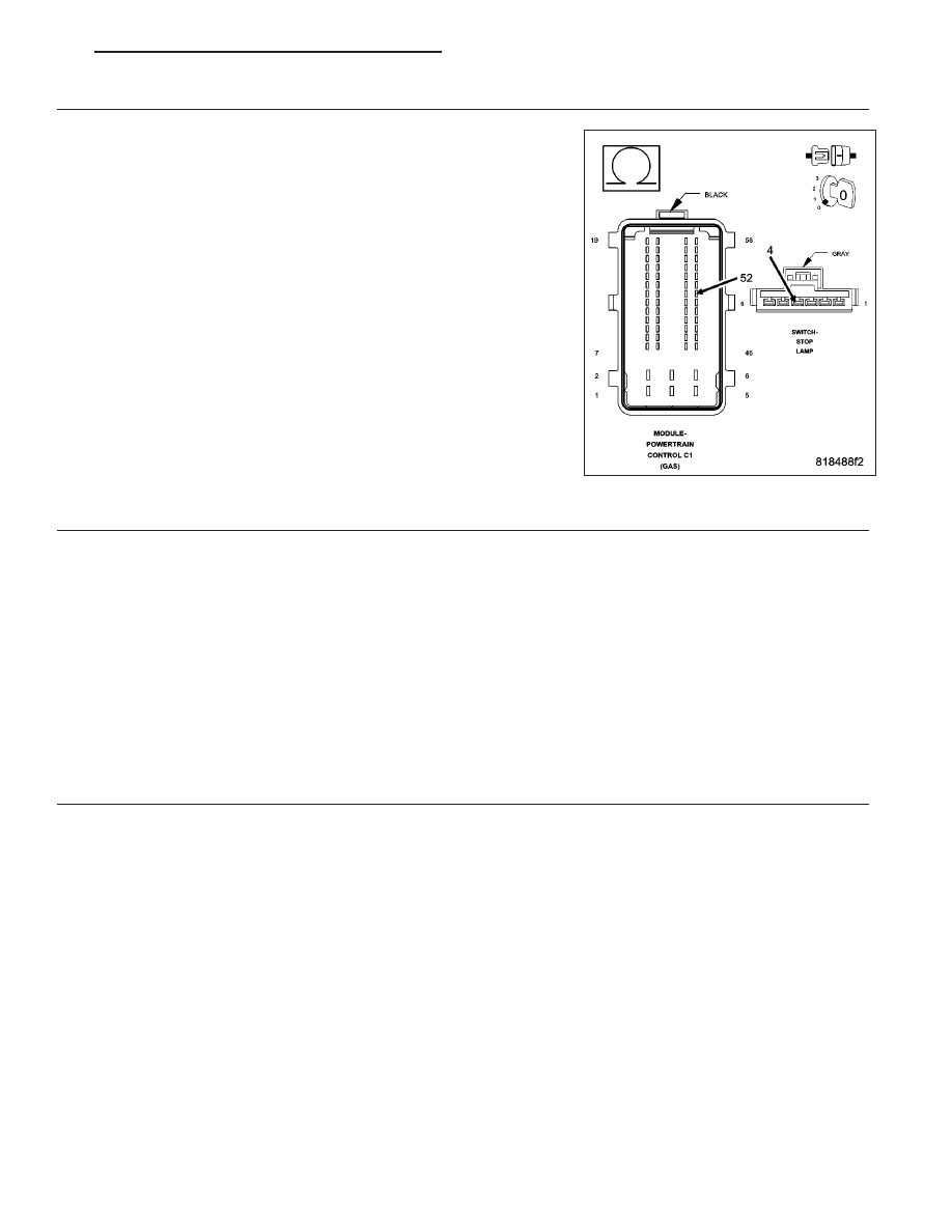
(B16) BRAKE SIGNAL 2 CIRCUIT OPEN OR HIGH RESISTANCE
Measure the resistance of the (B16) Brake Signal 2 circuit between the
Stop Lamp Switch harness connector and the Powertrain Control Mod-
ule (PCM) harness connector.
Is the resistance below 5.0 ohms?
Yes
>> Go to 10
No
>> Repair the (B16) Brake Signal 2 circuit for an open circuit or
high resistance.
Perform the PCM Verification Test Ver. 1 (Refer to 9 -
ENGINE - DIAGNOSIS AND TESTING).
10.
STOP LAMP SWITCH
Using the wiring diagram/schematic as a guide, inspect the wiring and connectors between the Stop Lamp Switch
and the Powertrain Control Module (PCM).
Look for any chafed, pierced, pinched, or partially broken wires.
Look for broken, bent, pushed out or corroded terminals.
Refer to any Technical Service Bulletins that may apply.
Were any problems found?
Yes
>> Repair as necessary.
Perform the PCM Verification Test Ver. 1 (Refer to 9 - ENGINE - DIAGNOSIS AND TESTING).
No
>> Replace the Stop Lamp Switch in accordance with the Service Information.
Perform the PCM Verification Test Ver. 1 (Refer to 9 - ENGINE - DIAGNOSIS AND TESTING).
11.
POWERTRAIN CONTROL MODULE (PCM)
Using the wiring diagram/schematic as a guide, inspect the wiring and connectors between the Stop Lamp Switch
and the Powertrain Control Module (PCM).
Look for any chafed, pierced, pinched, or partially broken wires.
Look for broken, bent, pushed out or corroded terminals.
Refer to any Technical Service Bulletins that may apply.
Were any problems found?
Yes
>> Repair as necessary.
Perform the PCM Verification Test Ver. 1 (Refer to 9 - ENGINE - DIAGNOSIS AND TESTING).
No
>> Replace and program the Powertrain Control Module (PCM) in accordance with the Service Information.
Perform the PCM Verification Test Ver. 1 (Refer to 9 - ENGINE - DIAGNOSIS AND TESTING).
PM
ENGINE ELECTRICAL DIAGNOSTICS - GPEC
9 - 651