Dodge Caliber. Manual - part 790


  Index      Dodge     Dodge Caliber - service repair manual 2007 year


Search            


Content   ..  788  789  790  791   ..


Dodge Caliber. Manual - part 790


14.

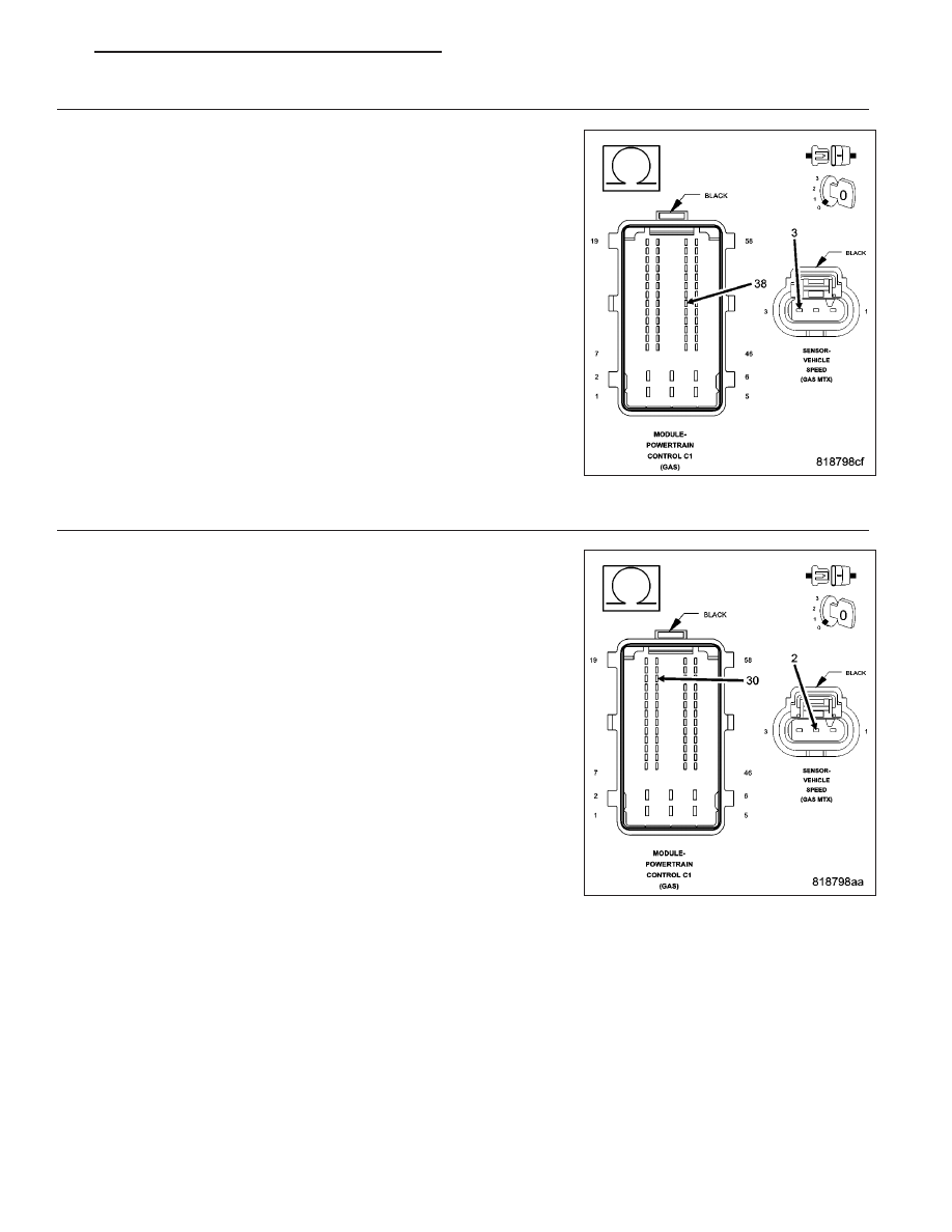
(K75) VEHICLE SPEED SIGNAL CIRCUIT OPEN OR HIGH RESISTANCE

Measure the resistance of the (K75) Vehicle Speed Signal circuit
between the Vehicle Speed Sensor harness connector and the Power-
train Control Module (PCM) harness connector.

Is the resistance below 5.0 ohms?

Yes

>> Go to 16

No

>> Repair the (K75) Vehicle Speed Signal circuit for an open

circuit or high resistance.

Perform the PCM Verification Test Ver. 1 (Refer to 9 -
ENGINE - DIAGNOSIS AND TESTING).

15.

(K914) SENSOR GROUND CIRCUIT OPEN OR HIGH RESISTANCE

Turn the ignition off.

Disconnect the Powertrain Control Module (PCM) connector.

Measure the resistance of the (K914) Sensor Ground circuit between
the Vehicle Speed Sensor harness connector and the Powertrain Con-
trol Module (PCM) harness connector.

Is the resistance below 5.0 ohms?

Yes

>> Go to 16

No

>> Repair the circuit for an open circuit or high resistance.

Perform the PCM Verification Test Ver. 1 (Refer to 9 -
ENGINE - DIAGNOSIS AND TESTING).

PM

ENGINE ELECTRICAL DIAGNOSTICS - GPEC

9 - 447

16.

POWERTRAIN CONTROL MODULE (PCM)

Using the wiring diagram/schematic as a guide, inspect the wiring and connectors between the Vehicle Speed Sen-
sor and the Powertrain Control Module (PCM).

Look for any chafed, pierced, pinched, or partially broken wires.

Look for broken, bent, pushed out or corroded terminals.

Monitor the scan tool data relative to this circuit and wiggle test the wiring and connectors.

Look for the data to change or for the DTC to reset during the wiggle test.

Refer to any Technical Service Bulletins that may apply.

Were any problems found?

Yes

>> Repair as necessary.

Perform the PCM Verification Test Ver. 1 (Refer to 9 - ENGINE - DIAGNOSIS AND TESTING).

No

>> Replace and program the Powertrain Control Module (PCM) in accordance with the Service Information.

Perform the PCM Verification Test Ver. 1 (Refer to 9 - ENGINE - DIAGNOSIS AND TESTING).

9 - 448

ENGINE ELECTRICAL DIAGNOSTICS - GPEC

PM

P0506-IDLE SPEED PERFORMANCE LOWER THAN EXCEPTED

For a complete wiring diagram Refer to Section 8W.

Theory of Operation

The objective of the Idle Speed Rationality monitor is to evaluate the ability of the idle speed control system to
achieve and maintain a steady idle, by monitoring engine RPM during idle. If engine RPM is not within a calibrated
deadband of target idle speed, a timer is started. If the timer reaches a maximum threshold without any sign of the
RPM trending towards control, a soft failure is generated.

When Monitored:
With the engine idling in drive (for CVT vehicles) with the brake applied, MAF < 250 mg/tdc, air temp > -17.8°
C (0° F) enable after coolant temp > 70° C (158° F), canister purge < 100% duty cycle, and no VSS, MAF/
MAP, ECT, TPS, ETC, CKP Sensor, fuel system, or injector DTCs present.

Set Condition:
Engine speed is 100 RPM or more below target idle speed for 30 seconds. Two Trip Fault. Three good trips
to turn off the MIL.

Possible Causes

AIR INDUCTION SYSTEM LEAKS OR RESTRICTIONS

PCV SYSTEM LEAKS OR RESTRICTIONS

THROTTLE BODY

POWERTRAIN CONTROL MODULE (PCM)

Always perform the Pre-Diagnostic Troubleshooting procedure before proceeding. (Refer to 9 - ENGINE -
DIAGNOSIS AND TESTING).

Diagnostic Test

1.

ACTIVE DTC

NOTE: It is possible for ETC DTCs to be set at the same time as this DTC. Proceed with this test only if the
other DTCs that are present are ETC related, but clear them before proceeding. If any other DTCs are set,
they must be diagnosed and repaired before continuing this test.
Ignition on, engine not running.

With a scan tool, select View DTCs.

Is the status Active for this DTC?

Yes

>> Go to 2

No

>> Refer to the *CHECKING FOR AN INTERMITTENT DTC Diagnostic Procedure. (Refer to 9 - ENGINE -

DIAGNOSIS AND TESTING)

2.

AIR INDUCTION SYSTEM

Inspect the air induction system for the following problems:

Restrictions - dirty air cleaner, foreign material trapped in the air intake tube, etc.

Leaks - air intake tube connection, air cleaner housing, etc.

Were any problems found?

Yes

>> Repair as necessary.

Perform the PCM Verification Test Ver. 1 (Refer to 9 - ENGINE - DIAGNOSIS AND TESTING)

No

>> Go to 3

PM

ENGINE ELECTRICAL DIAGNOSTICS - GPEC

9 - 449

3.

PCV SYSTEM

Inspect the PCV system for the following problems:

Restrictions - sticking valve, collapsed hoses or tubes, obstructed passages or ports, etc.

Leaks - cracked or damaged hoses or tubes, poor hose or tube connections, PCV valve stuck open, etc.

Were any problems found?

Yes

>> Repair as necessary.

Perform the PCM Verification Test Ver. 1 (Refer to 9 - ENGINE - DIAGNOSIS AND TESTING)

No

>> Go to 4

4.

THROTTLE BODY OPERATION

WARNING: When the engine is operating, do not stand in direct line with the fan. Do not put your hands
near the pulleys, belts, or fan. Do not wear loose clothing. Failure to follow these instructions can result in
personal injury or death.
Inspect the throttle body for carbon build up or other restrictions.

Using a straight edge, verify that the throttle plate is not bent. If the throttle plate is bent, the throttle body must be
replaced.

Start the engine.

While the engine is running, lightly tap on the ETC Motor, and listen for the idle to change.

Were any problems found?

Yes

>> Repair as necessary.

Perform the PCM Verification Test Ver. 1 (Refer to 9 - ENGINE - DIAGNOSIS AND TESTING)

No

>> Go to 5

5.

POWERTRAIN CONTROL MODULE (PCM)

Using the wiring diagram/schematic as a guide, inspect the wiring and connectors between the throttle body and the
PCM.

Look for any chafed, pierced, pinched, or partially broken wires.

Look for broken, bent, pushed out or corroded terminals.

Refer to any Technical Service Bulletins that may apply.

Were any problems found?

Yes

>> Repair as necessary.

Perform the PCM Verification Test Ver. 1 (Refer to 9 - ENGINE - DIAGNOSIS AND TESTING)

No

>> Replace and program the Powertrain Control Module (PCM) in accordance with the Service Information.

Perform the PCM Verification Test Ver. 1 (Refer to 9 - ENGINE - DIAGNOSIS AND TESTING)

9 - 450

ENGINE ELECTRICAL DIAGNOSTICS - GPEC

PM


Content   ..  788  789  790  791   ..