Dodge Caliber. Manual - part 775
4.
EVAP PURGE HOSE/TUBE OBSTRUCTION
Inspect the Evap Purge hose/tube for proper routing and installation between the EVAP Purge Solenoid and the
Fuel Tank and between the Fuel Tank and the Evap Purge Canister.
Make sure the hose/tube is not damaged or kinked and is free from any obstructions or blockage.
Were any problems found?
Yes
>> Repair or replace as necessary.
Perform the PCM Verification Test Ver. 1 (Refer to 9 - ENGINE - DIAGNOSIS AND TESTING).
No
>> Go to 5
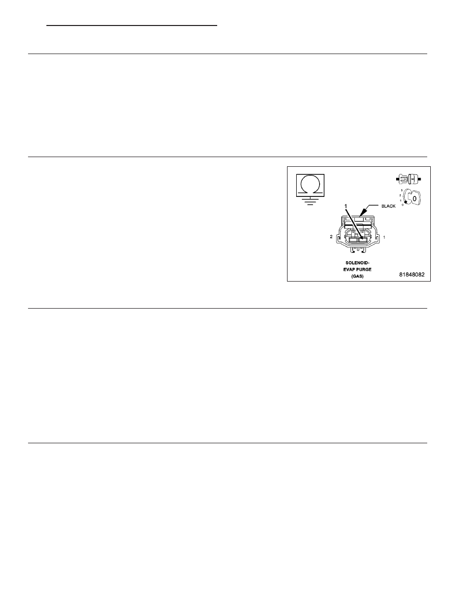
5.
(K52) EVAP PURGE CONTROL CIRCUIT SHORTED TO GROUND
Turn the ignition off.
Disconnect the PCM harness connector.
Measure the resistance between ground and the (K52) Evap Purge
Control circuit in the EVAP Purge Solenoid harness connector.
Is the resistance below 100 ohms?
Yes
>> Repair the (K52) Evap Purge Control circuit for a short to
ground.
Perform the PCM Verification Test Ver. 1 (Refer to 9 -
ENGINE - DIAGNOSIS AND TESTING).
No
>> Go to 6
6.
EVAP PURGE SOLENOID
Using the wiring diagram/schematic as a guide, inspect the wiring and connectors between the Evap Purge Sole-
noid and the Powertrain Control Module (PCM).
Look for any chafed, pierced, pinched, or partially broken wires.
Look for broken, bent, pushed out or corroded terminals.
Refer to any Technical Service Bulletins that may apply.
Were any problems found?
Yes
>> Repair as necessary.
Perform the PCM Verification Test Ver. 1 (Refer to 9 - ENGINE - DIAGNOSIS AND TESTING).
No
>> Replace the Evap Purge Solenoid in accordance with the Service Information.
Perform the PCM Verification Test Ver. 1 (Refer to 9 - ENGINE - DIAGNOSIS AND TESTING).
7.
ESIM ASSEMBLY
With a scan tool, select Data Display and view the ESIM Switch state.
Disconnect the Evap System Monitor Switch electrical connector.
Does the ESIM Switch state change from CLOSED to OPEN when the switch is disconnected?
Yes
>> Replace the ESIM Assembly.
Perform the PCM Verification Test Ver. 1 (Refer to 9 - ENGINE - DIAGNOSIS AND TESTING).
No
>> Go to 8
PM
ENGINE ELECTRICAL DIAGNOSTICS - GPEC
9 - 387