Dodge Caliber. Manual - part 695


  Index      Dodge     Dodge Caliber - service repair manual 2007 year


Search            


Content   ..  693  694  695  696   ..


Dodge Caliber. Manual - part 695


9.

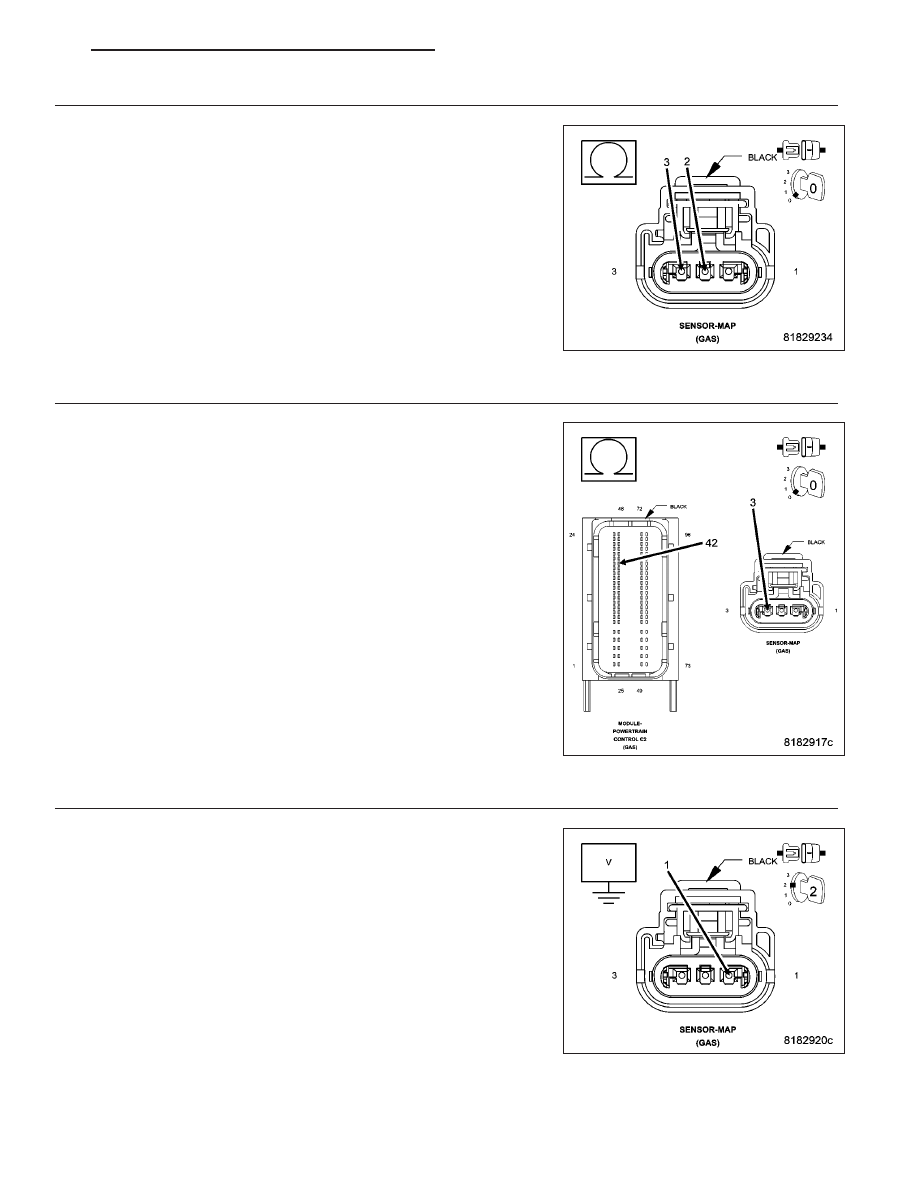
(K857) 5 VOLT SUPPLY CIRCUIT SHORTED TO THE (K900) SENSOR GROUND CIRCUIT

Measure the resistance between the (K857) 5 Volt Supply circuit and
the (K900) Sensor Ground circuit in the MAP Sensor harness connec-
tor.

Is the resistance above 100 ohms?

Yes

>> Go to 10

No

>> Repair the (K857) 5 Volt Supply circuit for a short to the

(K900) Sensor Ground circuit.

Perform the PCM Verification Test Ver. 1 (Refer to 9 -
ENGINE - DIAGNOSIS AND TESTING).

10.

(K857) 5 VOLT SUPPLY CIRCUIT OPEN OR HIGH RESISTANCE

Measure the resistance of the (K857) 5 Volt Supply circuit between the
MAP Sensor harness connector and the Powertrain Control Module
(PCM) harness connector.

Is the resistance below 5.0 ohms?

Yes

>> Go to 16

No

>> Repair the (K857) 5 Volt Supply circuit for an open circuit or

high resistance.

Perform the PCM Verification Test Ver. 1 (Refer to 9 -
ENGINE - DIAGNOSIS AND TESTING).

11.

(K1) MAP SIGNAL CIRCUIT SHORTED TO VOLTAGE

Turn the ignition off.

Disconnect the Powertrain Control Module (PCM) connector.

Turn the ignition on.

Measure the voltage of the (K1) MAP Signal circuit in the MAP Sensor
harness connector.

Is there any voltage present?

Yes

>> Repair the (K1) MAP Signal circuit for a short to voltage.

Perform the PCM Verification Test Ver. 1 (Refer to 9 -
ENGINE - DIAGNOSIS AND TESTING).

No

>> Go to 12

PM

ENGINE ELECTRICAL DIAGNOSTICS - GPEC

9 - 67

12.

(K1) MAP SIGNAL CIRCUIT SHORTED TO GROUND

Turn the ignition off.

Measure the resistance between ground and the (K1) MAP Signal cir-
cuit in the MAP Sensor harness connector.

Is the resistance above 100 ohms?

Yes

>> Go to 13

No

>> Repair the (K1) MAP Signal circuit for a short to ground.

Perform the PCM Verification Test Ver. 1 (Refer to 9 -
ENGINE - DIAGNOSIS AND TESTING).

13.

(K1) MAP SIGNAL CIRCUIT SHORTED TO (K900) SENSOR GROUND CIRCUIT

Measure the resistance between the (K1) MAP Signal circuit and the
(K900) Sensor Ground circuit in the MAP Sensor harness connector.

Is the resistance above 100 ohms?

Yes

>> Go to 14

No

>> Repair the (K1) MAP Signal circuit for a short to the (K900)

Sensor Ground circuit.

Perform the PCM Verification Test Ver. 1 (Refer to 9 -
ENGINE - DIAGNOSIS AND TESTING).

14.

(K1) MAP SIGNAL CIRCUIT OPEN OR HIGH RESISTANCE

Measure the resistance of the (K1) MAP Signal circuit between the
MAP Sensor harness connector and the Powertrain Control Module
(PCM) harness connector.

Is the resistance below 5.0 ohms?

Yes

>> Go to 16

No

>> Repair the (K1) MAP Signal circuit for an open circuit or

high resistance.

Perform the PCM Verification Test Ver. 1 (Refer to 9 -
ENGINE - DIAGNOSIS AND TESTING).

9 - 68

ENGINE ELECTRICAL DIAGNOSTICS - GPEC

PM

15.

(K900) SENSOR GROUND CIRCUIT OPEN OR HIGH RESISTANCE

Turn the ignition off.

Disconnect the Powertrain Control Module (PCM) connector.

Measure the resistance of the (K900) Sensor Ground circuit between
the MAP Sensor harness connector and the Powertrain Control Module
(PCM) harness connector.

Is the resistance below 5.0 ohms?

Yes

>> Go to 16

No

>> Repair the circuit for an open circuit or high resistance.

Perform the PCM Verification Test Ver. 1 (Refer to 9 -
ENGINE - DIAGNOSIS AND TESTING).

16.

POWERTRAIN CONTROL MODULE (PCM)

Using the wiring diagram/schematic as a guide, inspect the wiring and connectors between the MAP Sensor and the
Powertrain Control Module (PCM).

Look for any chafed, pierced, pinched, or partially broken wires.

Look for broken, bent, pushed out or corroded terminals.

Monitor the scan tool data relative to this circuit and wiggle test the wiring and connectors.

Look for the data to change or for the DTC to reset during the wiggle test.

Refer to any Technical Service Bulletins that may apply.

Were any problems found?

Yes

>> Repair as necessary.

Perform the PCM Verification Test Ver. 1 (Refer to 9 - ENGINE - DIAGNOSIS AND TESTING).

No

>> Replace and program the Powertrain Control Module (PCM) in accordance with the Service Information.

Perform the PCM Verification Test Ver. 1 (Refer to 9 - ENGINE - DIAGNOSIS AND TESTING).

PM

ENGINE ELECTRICAL DIAGNOSTICS - GPEC

9 - 69

P0107-MANIFOLD ABSOLUTE PRESSURE SENSOR CIRCUIT LOW

For a complete wiring diagram Refer to Section 8W

9 - 70

ENGINE ELECTRICAL DIAGNOSTICS - GPEC

PM


Content   ..  693  694  695  696   ..