Dodge Caliber. Manual - part 537


  Index      Dodge     Dodge Caliber - service repair manual 2007 year


Search            


Content   ..  535  536  537  538   ..


Dodge Caliber. Manual - part 537


WIPERS/WASHERS - SERVICE INFORMATION

DESCRIPTION

FRONT

An electrically operated intermittent front wiper and washer system is standard factory-installed safety equipment on
this vehicle. The wiper and washer system includes the following major components, which are described in further
detail elsewhere in this service information:

ElectroMechanical Instrument Cluster - The ElectroMechanical Instrument Cluster (EMIC) (also known as
the Cab Compartment Node/CCN) is located on the instrument panel directly in front of the driver. (Refer to 8
- ELECTRICAL/INSTRUMENT CLUSTER - DESCRIPTION).

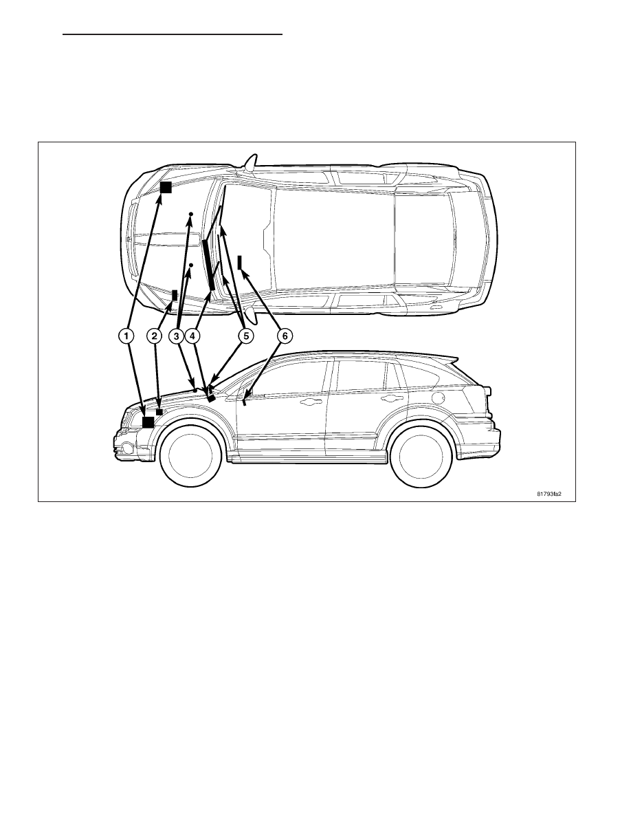
Front Washer Nozzle (3) - Two fluidic front washer nozzles with integral check valves are secured by latch
features to dedicated openings in the hood panel near the base of the windshield.

Front Washer Plumbing - The plumbing for the washer system consists of rubber hoses and molded rubber
or plastic fittings. The plumbing is routed to the engine compartment from the washer reservoir. The front
washer hose is routed along the right side of the engine compartment to the cowl plenum panel, then across
the underside of the inner hood panel reinforcement to the washer nozzles.

Front Wiper Arms And Blades (5) - The two front wiper arms are secured with nuts to the threaded ends of
the two wiper pivot shafts, which extend through the cowl plenum cover/grille panel located near the base of
the windshield. The two unequal length front wiper blades are each secured to their wiper arm with an integral
latch, and are parked on the glass near the bottom of the windshield when the front wiper system is not in
operation.

Front Wiper Module (4) - The wiper pivot shafts are the only visible components of the front wiper module.
The remainder of the module is concealed within the cowl plenum beneath the cowl plenum cover/grille panel.
The wiper module includes the wiper module bracket, three rubber-isolated wiper module mounts, the wiper
motor, the wiper motor crank arm, the two wiper drive links, the two wiper pivots and the two pivot water
shields.

PM

WIPERS/WASHERS - SERVICE INFORMATION

8R - 19

Right Multi-Function Switch (6) - The right (wiper) multi-function switch and the left (lighting) multi-function
switch are secured to brackets integral to the clockspring housing on the top of the steering column just below
the steering wheel. The right multi-function switch is connected by a short jumper harness to the Steering
Control Module (SCM), which is internal to the left multi-function switch housing. Only the switch control stalk
extending from the right side of the steering column is visible, while the remainder of the switch is concealed
beneath the steering column shrouds. The right multi-function switch is dedicated to providing all of the driver
controls for both the front and rear wiper and washer systems.

Steering Control Module - The Steering Control Module (SCM) is internal to the left multi-function switch
housing, which is secured to a bracket integral to the left side of the clockspring housing on the top of the
steering column just below the steering wheel. Only the left switch control stalk extending from the left side of
the steering column is visible, while the remainder of the switch housing containing the SCM is concealed
beneath the steering column shrouds. (Refer to 8 - ELECTRICAL/ELECTRONIC CONTROL MODULES/
STEERING COLUMN CONTROL MODULE - DESCRIPTION).

Totally Integrated Power Module (2) - The Totally Integrated Power Module (TIPM) is located in the engine
compartment, near the battery. (Refer to 8 - ELECTRICAL/POWER DISTRIBUTION/TOTALLY INTEGRATED
POWER MODULE - DESCRIPTION).

Washer Pump/Motor - The reversible electric washer pump/motor unit is located in a dedicated hole in a
sump area on the lower, forward facing surface of the washer reservoir, ahead of the right front wheel house.
This single reversible washer pump/motor provides washer fluid to either the front or rear washer system
plumbing, depending upon the direction of the pump motor rotation.

Washer Reservoir (1) - The washer reservoir is located in the engine compartment ahead of the right front
strut tower and wheel house. The filler neck and cap are accessed from the right front corner of the engine
compartment.

8R - 20

WIPERS/WASHERS - SERVICE INFORMATION

PM

REAR

An electrically operated fixed interval intermittent rear wiper and washer system is standard factory-installed equip-
ment on this vehicle. The rear wiper and washer system includes the following major components, which are
described in further detail elsewhere in this service information:

ElectroMechanical Instrument Cluster - The ElectroMechanical Instrument Cluster (EMIC) (also known as
the Cab Compartment Node/CCN) is located on the instrument panel directly in front of the driver. (Refer to 8
- ELECTRICAL/INSTRUMENT CLUSTER - DESCRIPTION).

Rear Washer Nozzle (4) - The fluidic rear washer nozzle is integrated into the rear spoiler on the liftgate outer
panel above the liftgate glass and is located to the right of the Center High-Mounted Stop Lamp (CHMSL).

Rear Washer Plumbing - The plumbing for the rear washer system consists of rubber hoses, molded plastic
fittings and a rear washer system check valve. The plumbing is routed along the right side of the engine com-
partment from the washer reservoir, through the dash into the passenger compartment, up the right cowl side
and A-pillar to the headliner then through the upper liftgate opening header and the upper liftgate to the rear
washer nozzle on the upper liftgate spoiler. The rear washer system check valve (3) connects the headliner
washer hose to the liftgate washer hose and is located near the upper liftgate opening header behind the right
upper D-pillar trim.

Rear Wiper Arm And Blade (5) - The single rear wiper arm is secured by a nut directly to the rear wiper
motor output shaft, which extends through a rubber grommet inserted into a hole in the center at the base of
the liftgate glass. The rear wiper blade is secured to the rear wiper arm with an integral latch, and is parked
near the base of the glass when the rear wiper system is not in operation.

Rear Wiper Motor (6) - The rear wiper motor includes the motor bracket and three rubber-isolated wiper motor
mounts. The wiper motor output shaft is the only visible component of the rear wiper motor. The remainder of
the motor is concealed by the inner liftgate trim on the inside of the liftgate beneath the liftgate glass opening.

Right Multi-Function Switch (2) - The right (wiper) multi-function switch and the left (lighting) multi-function
switch are secured to brackets integral to the clockspring housing, on the top of the steering column just below
the steering wheel. The right multi-function switch is connected by a short jumper harness to the Steering
Control Module (SCM), which is internal to the left multi-function switch housing. Only the switch control stalk

PM

WIPERS/WASHERS - SERVICE INFORMATION

8R - 21

extending from the right side of the steering column is visible, while the remainder of the switch is concealed
beneath the steering column shrouds. The right multi-function switch is dedicated to providing all of the driver
controls for both the front and rear wiper and washer systems.

Steering Control Module - The Steering Control Module (SCM) is internal to the left multi-function switch
housing, which is secured to a bracket integral to the left side of the clockspring housing on the top of the
steering column just below the steering wheel. Only the left switch control stalk extending from the left side of
the steering column is visible, while the remainder of the switch housing containing the SCM is concealed
beneath the steering column shrouds. (Refer to 8 - ELECTRICAL/ELECTRONIC CONTROL MODULES/
STEERING COLUMN CONTROL MODULE - DESCRIPTION).

Totally Integrated Power Module (1) - The Totally Integrated Power Module (TIPM) is located in the engine
compartment, near the battery. (Refer to 8 - ELECTRICAL/POWER DISTRIBUTION/TOTALLY INTEGRATED
POWER MODULE - DESCRIPTION).

Washer Reservoir - The rear washer system shares a single reservoir and reversible pump with the front
washer system, but has its own dedicated plumbing. The washer reservoir is located in the engine compart-
ment ahead of the right front strut tower and wheel house. The filler neck and cap are accessed from the right
front corner of the engine compartment.

OPERATION

FRONT

The front wiper and washer system is designed to pro-
vide the vehicle operator with a convenient, safe, and
reliable means of maintaining visibility through the
windshield glass. The various components of this sys-
tem are designed to convert electrical energy pro-
duced by the vehicle electrical system into the
mechanical action of the wiper blades to wipe the out-
side surface of the glass, as well as into the hydraulic
action of the washer system to apply washer fluid
stored in an on-board reservoir to the area of the
glass to be wiped. When combined, these compo-
nents provide the means to effectively maintain clear
visibility for the vehicle operator by removing excess
accumulations of rain, snow, bugs, mud, or other
minor debris from the outer surface of the windshield
glass that might be encountered while driving the vehi-
cle under numerous types of inclement operating
conditions.

The vehicle operator initiates all front and rear wiper and washer system functions with the control stalk of the right
(wiper) multi-function switch (1) that extends from the right side of the steering column, just below the steering
wheel. Rotating the control knob (2) on the end of the control stalk, selects the OFF, DELAY, LOW, or HIGH front
wiper system operating modes. In the DELAY mode, the control knob also allows the vehicle operator to select from
one of five intermittent wipe delay intervals.

Pulling the control stalk rearward actuates the momentary front washer system switch, which selects the WASH and
WIPE-AFTER-WASH modes, depending upon when and how long the switch is held closed. Pushing the control
stalk downward actuates a momentary switch and selects the MIST mode, which cycles the wiper blades for as long
as the switch is held closed then completes the current cycle and parks the blades at the base of the windshield
after the switch is released.

The right multi-function switch provides hard wired analog and resistor multiplexed inputs to the Steering Control
Module (SCM) internal to the left (lighting) multi-function switch housing for all of the wiper and washer system
functions. The SCM then sends electronic wiper and washer switch status messages to the ElectroMechanical
Instrument Cluster (EMIC) (also known as the Cab Compartment Node/CCN), over a Local Interconnect Network
(LIN) data bus. The EMIC responds to the SCM inputs by sending electronic wiper and washer system request
messages to the Totally Integrated Power Module (TIPM) over the Controller Area Network (CAN) data bus request-
ing the appropriate wiper and washer system operating modes.

8R - 22

WIPERS/WASHERS - SERVICE INFORMATION

PM


Content   ..  535  536  537  538   ..