Dodge Caliber. Manual - part 532


  Index      Dodge     Dodge Caliber - service repair manual 2007 year


Search            


Content   ..  530  531  532  533   ..


Dodge Caliber. Manual - part 532


REMOVAL

1. Disconnect and isolate the battery negative cable.

2. Remove the right front wheel well splash shield

(Refer to 23 - BODY/EXTERIOR/FRONT END
SPLASH SHIELDS - REMOVAL).

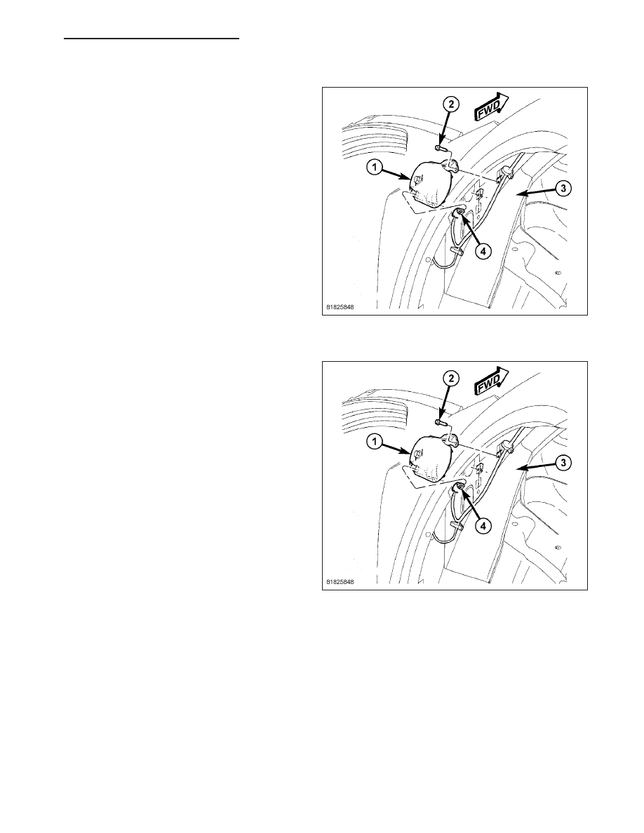
3. Disconnect the electrical connector (4).

4. Remove the siren retaining screws (2) and remove

the siren (1) from the load form (3).

INSTALLATION

1. Position siren (1) on load form and install retaining

screws (2).

2. Connect the siren electrical connector (4).

3. Install the right front wheel well splash shield

(Refer to 23 - BODY/EXTERIOR/FRONT END
SPLASH SHIELDS - INSTALLATION).

4. Connect the battery negative cable.

PM

VEHICLE THEFT SECURITY - SERVICE INFORMATION

8Q - 105

TRANSPONDER KEY

DESCRIPTION

Each ignition key (2) used in the Sentry Key Remote
Entry System (SKREES) has a transponder chip
included on the circuit board (4) beneath the cover (1)
of the integral Remote Keyless Entry (RKE) transmit-
ter (3). In addition to having to be cut to match the
mechanical coding of the ignition lock cylinder and
programmed for operation of the RKE system, each
new Sentry Key has a unique transponder identifica-
tion code that is permanently programmed into it by
the manufacturer, and which must be programmed
into the Sentry Key REmote Entry Module (SKREEM),
sometimes referred to as the Wireless Control Module
(WCM), to be recognized by the SKREES as a valid
key. The Sentry Key transponder cannot be adjusted
or repaired. If faulty or damaged, the entire key and
RKE transmitter unit must be replaced.

OPERATION

When the ignition switch is turned to the On position, the Sentry Key REmote Entry Module (SKREEM), sometimes
referred to as the Wireless Control Module (WCM), communicates through its antenna with the Sentry Key tran-
sponder using a Radio Frequency (RF) signal. The SKREEM/WCM then listens for a RF response from the tran-
sponder through the same antenna. The Sentry Key transponder chip is within the range of the SKREEM/WCM
transceiver antenna ring when it is inserted into the ignition lock cylinder. The SKREEM/WCM determines whether
a valid key is present in the ignition lock cylinder based upon the response from the transponder. If a valid key is
detected, that fact is communicated by the SKREEM/WCM to the Powertrain Control Module (PCM) over the Con-
troller Area Network (CAN) data bus, and the PCM allows the engine to continue running. If the PCM receives an
invalid key message, or receives no message from the SKREEM/WCM over the CAN data bus, the engine will be
disabled after about two seconds of operation. The ElectroMechanical Instrument Cluster (EMIC), sometimes
referred to as the Cab Compartment Node (CCN), will also respond to the invalid key message on the CAN data
bus by flashing the security indicator on and off.

Each Sentry Key has a unique transponder identification code permanently programmed into it by the manufacturer.
Likewise, the SKREEM/WCM has a unique Secret Key code programmed into it by the manufacturer. When a Sen-
try Key is programmed into the memory of the SKREEM/WCM, the SKREEM/WCM stores the transponder identi-
fication code from the Sentry Key, and the Sentry Key learns the Secret Key code from the SKREEM/WCM. Once
the Sentry Key learns the Secret Key code of the SKREEM/WCM, it is permanently stored in the memory of the
transponder. Therefore, once a Sentry Key has been programmed to a particular vehicle, it cannot be used on any
other vehicle (Refer to 8 - ELECTRICAL/VEHICLE THEFT SECURITY/TRANSPONDER KEY - STANDARD PRO-
CEDURE).

The Sentry Key REmote Entry System (SKREES) performs a self-test each time the ignition switch is turned to the
On position, and will store key-related fault information in the form of a Diagnostic Trouble Code (DTC) in SKREEM/
WCM memory if a Sentry Key transponder problem is detected. The Sentry Key transponder chip can be diag-
nosed, and any stored DTC can be retrieved using a diagnostic scan tool. Refer to the appropriate diagnostic
information.

Common communication problems:

Two transponder keys too close together.

Speed Pass too close to transponder key.

Loss of PCM communication.

Failed antenna circuit.

8Q - 106

VEHICLE THEFT SECURITY - SERVICE INFORMATION

PM

WIPERS/WASHERS - ELECTRICAL DIAGNOSTICS

DIAGNOSIS AND TESTING

8R - 2

WIPERS/WASHERS - ELECTRICAL DIAGNOSTICS

PM


Content   ..  530  531  532  533   ..