Dodge Caliber. Manual - part 502


  Index      Dodge     Dodge Caliber - service repair manual 2007 year


Search            


Content   ..  500  501  502  503   ..


Dodge Caliber. Manual - part 502


REAR SEAT BELT BUCKLE

REMOVAL

CENTER/LEFT BUCKLE

1. Remove the rear seat cushion (Refer to 23 -

BODY/SEATS/REAR

SEAT

CUSHION

-

REMOVAL)

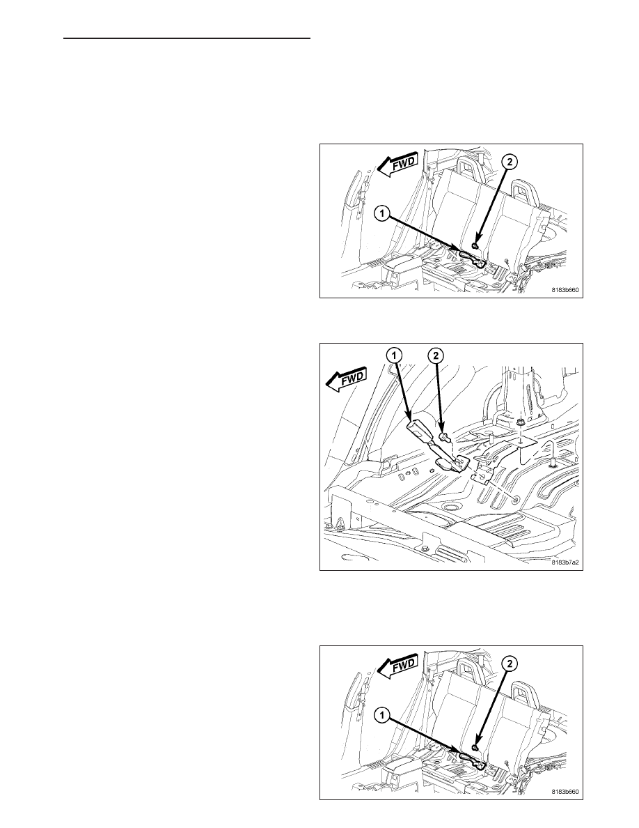
2. Remove the left and center seatbelt buckle retain-

ing bolt (2).

3. Remove the left and center seatbelt buckle (1) from

the vehicle.

RIGHT BUCKLE/CENTER SEAT BELT ANCHOR LATCH

1. Remove the rear seat cushion (Refer to 23 -

BODY/SEATS/REAR

SEAT

CUSHION

-

REMOVAL).

2. Remove the right buckle/center seatbelt anchor

latch retaining bolt (2).

3. Remove the right buckle/center seatbelt anchor

latch (1) from the vehicle.

INSTALLATION

CENTER/LEFT BUCKLE

1. Position the buckle (1) over the left inner seat back

hinge and install the retaining bolt (2). Tighten bolt
to 56 N·m (41.5 ft. lbs.).

2. Install the rear seat cushion (Refer to 23 - BODY/

SEATS/REAR SEAT CUSHION - INSTALLATION).

PM

RESTRAINTS - SERVICE INFORMATION

8O - 405

RIGHT BUCKLE/CENTER SEAT BELT ANCHOR LATCH

1. Position the right buckle/center seatbelt anchor

latch (1) in the vehicle.

2. Install the right buckle/center seatbelt anchor latch

retaining bolt (2). Tighten bolt to 56 N·m (41.5 ft.
lbs.).

3. Install the rear seat cushion (Refer to 23 - BODY/

SEATS/REAR SEAT CUSHION - INSTALLATION).

8O - 406

RESTRAINTS - SERVICE INFORMATION

PM

SEAT BELT-TENSIONER

DESCRIPTION

Seat belt tensioners supplement the dual front airbags for this vehicle. The seat belt tensioners are integral to the
front outboard seat belt retractor units, which are secured to the inner B-pillar on the right and left sides of the
vehicle. The retractor is concealed beneath the molded plastic inner B-pillar trim.

The seat belt tensioner consists primarily of a sprocket/pinion, a steel tube, a cast metal housing, numerous steel
balls, a stamped metal ball trap, a torsion bar and a small pyrotechnically activated gas generator with a connector
receptacle. All of these components are located on one side of the retractor spool on the outside of the retractor
housing except for the torsion bar, which serves as the spindle upon which the retractor spool rides. The seat belt
tensioners are controlled by the Occupant Restraint Controller (ORC) and are connected to the vehicle electrical
system through a dedicated take out of the body wire harness by a keyed and latching yellow molded plastic con-
nector insulator to ensure a secure connection.

The seat belt tensioners cannot be repaired and, if ineffective or damaged, the entire front seat belt and retractor
unit must be replaced. If the front airbags have been deployed, the seat belt tensioners have also been deployed.
The seat belt tensioners are not intended for reuse and must be replaced following any front airbag deployment. A
growling or grinding sound while attempting to operate the seat belt retractor is a sure indication that the seat belt
tensioner has been deployed and requires replacement (Refer to 8 - ELECTRICAL/RESTRAINTS/FRONT SEAT
BELT & RETRACTOR - REMOVAL).

OPERATION

The seat belt tensioners are deployed in conjunction with the dual front airbags by a signal generated by the Occu-
pant Restraint Controller (ORC) through the driver or passenger seat belt tensioner line 1 and line 2 (or squib)
circuits. When the ORC sends the proper electrical signal to the tensioners, the electrical energy generates enough
heat to initiate a small pyrotechnic gas generator.

The gas generator is installed in one end of a steel tube that contains numerous steel balls. As the gas expands,
it pushes the steel balls through the tube into a cast metal housing, where a ball guide directs the balls into engage-
ment with the teeth of a sprocket that is geared to one end of the retractor spool. As the balls drive past the
sprocket, the sprocket turns and drives the seat belt retractor spool causing the slack to be removed from the front
seat belts. The ball trap captures the balls as they leave the sprocket and are expelled from the housing.

Removing excess slack from the front seat belts not only keeps the occupants properly positioned for an airbag
deployment following a frontal impact of the vehicle, but also helps to reduce injuries that the occupant might expe-
rience in these situations as a result of harmful contact with the steering wheel, steering column, instrument panel
or windshield. Also, the seat belt tensioner torsion bar that the retractor spool rides upon is designed to deform in
order to control the loading being applied to the occupants by the seat belts during a frontal impact, further reducing
the potential for occupant injuries.

The ORC monitors the condition of the seat belt tensioners through circuit resistance, and will illuminate the airbag
indicator in the ElectroMechanical Instrument Cluster (EMIC) (also known as the Cab Compartment Node/CCN) and
store a Diagnostic Trouble Code (DTC) for any fault that is detected. Proper diagnosis of the seat belt tensioner gas
generator and the seat belt tensioner squib circuits requires the use of a diagnostic scan tool. Refer to the appro-
priate diagnostic information.

PM

RESTRAINTS - SERVICE INFORMATION

8O - 407

SENSOR-SEAT WEIGHT

DESCRIPTION

The seat weight sensors are strain gauge-type units.
The electronic elements of the sensor are encased
within the sensor body (4). Four sensors are used in
the Occupant Classification System (OCS). The sen-
sors are located below the seat cushion between the
seat adjuster track and the seat adjuster riser at each
corner of the passenger side front seat.

A threaded mounting stud (2) on each sensor body is
secured by a nut to the seat adjuster riser, and two
nuts secure each sensor mounting flange (1) to two
studs integral to the front and rear of the inboard and
outboard passenger side lower seat adjuster tracks. A
molded connector receptacle (3) integral to each sen-
sor body is oriented towards the center of the seat
and is connected to the vehicle electrical system
through a dedicated connector and take out of the
passenger seat wire harness beneath the seat cush-
ion.

The seat weight sensors cannot be adjusted or
repaired and, if faulty or damaged, the entire sensor must be replaced.

OPERATION

The seat weight sensor units are designed to sense the relative weight of a load applied to the passenger side front
seat, which provides a logic input to the microprocessor of the Occupant Classification Module (OCM). When any
load is applied to the seat the load is transmitted through the sensor mounting flange to the sensor body (strain
gauge) of each sensor, causing a change of electrical resistance through the strain gauge. These changes in resis-
tance within the internal sensor circuitry change the sensor output voltage.

Each weight sensor receives a nominal five volts and a clean ground through parallel hard wired circuits from the
OCM. The OCM then monitors the output voltage of each sensor on dedicated hard wired data communication
circuits. The hard wired circuits between the sensors and the OCM may be diagnosed and tested using conven-
tional diagnostic tools and procedures. However, the most reliable, efficient, and accurate means to diagnose the
seat weight sensor inputs to the OCM, and the electronic message communication between the OCM and the Occu-
pant Restraint Controller (ORC) requires the use of a diagnostic scan tool. Refer to the appropriate diagnostic infor-
mation.

REMOVAL

WARNING: To avoid personal injury or death, never strike or drop a seat weight sensor or the passenger
side front seat assembly to which the sensors are secured as it can damage the sensors or affect their
calibration. The seat weight sensors and the passenger side front seat assembly must be handled with care
to avoid damage to the sensors. Do not sit upon or place any loads upon a passenger side front seat while
it is removed from its mounts in or outside of the vehicle. If an individual sensor is dropped or damaged,
replace the sensor with a new and unused unit. If a seat has been dropped during removal or loaded while
removed from its mounts, replace each of the seat weight sensors with new and unused units. Failure to
observe this warning could result in an accidental, incomplete, or improper passenger side front supple-
mental restraint deployment.

8O - 408

RESTRAINTS - SERVICE INFORMATION

PM


Content   ..  500  501  502  503   ..