Dodge Caliber. Manual - part 350
B1643-REAR LEFT TURN CONTROL CIRCUIT LOW
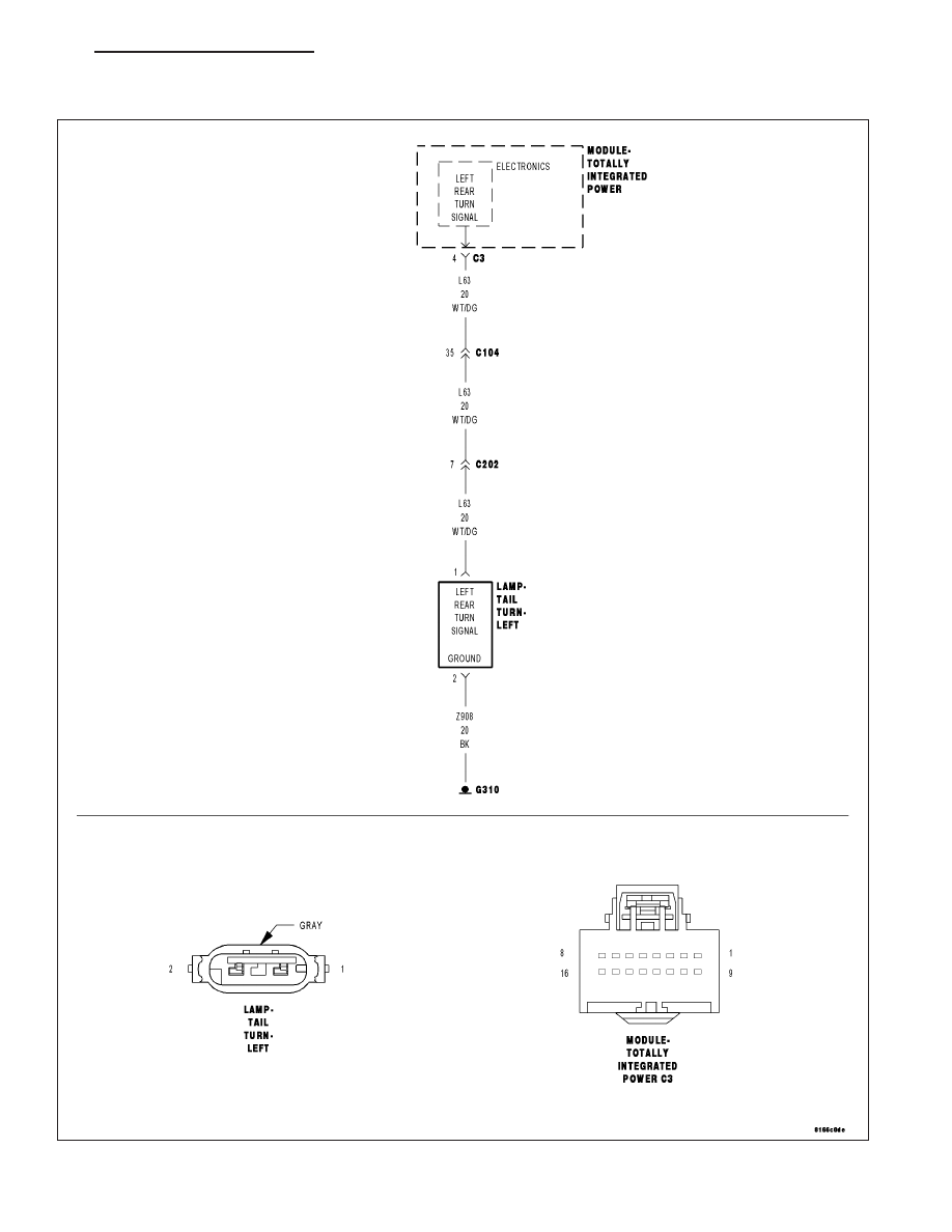
For a complete wiring diagram Refer to Section 8W.
PM
LAMPS/LIGHTING - EXTERIOR - ELECTRICAL DIAGNOSTICS
8L - 33
|
|
|
B1643-REAR LEFT TURN CONTROL CIRCUIT LOW For a complete wiring diagram Refer to Section 8W. PM LAMPS/LIGHTING - EXTERIOR - ELECTRICAL DIAGNOSTICS 8L - 33 |