Dodge Caliber. Manual - part 336
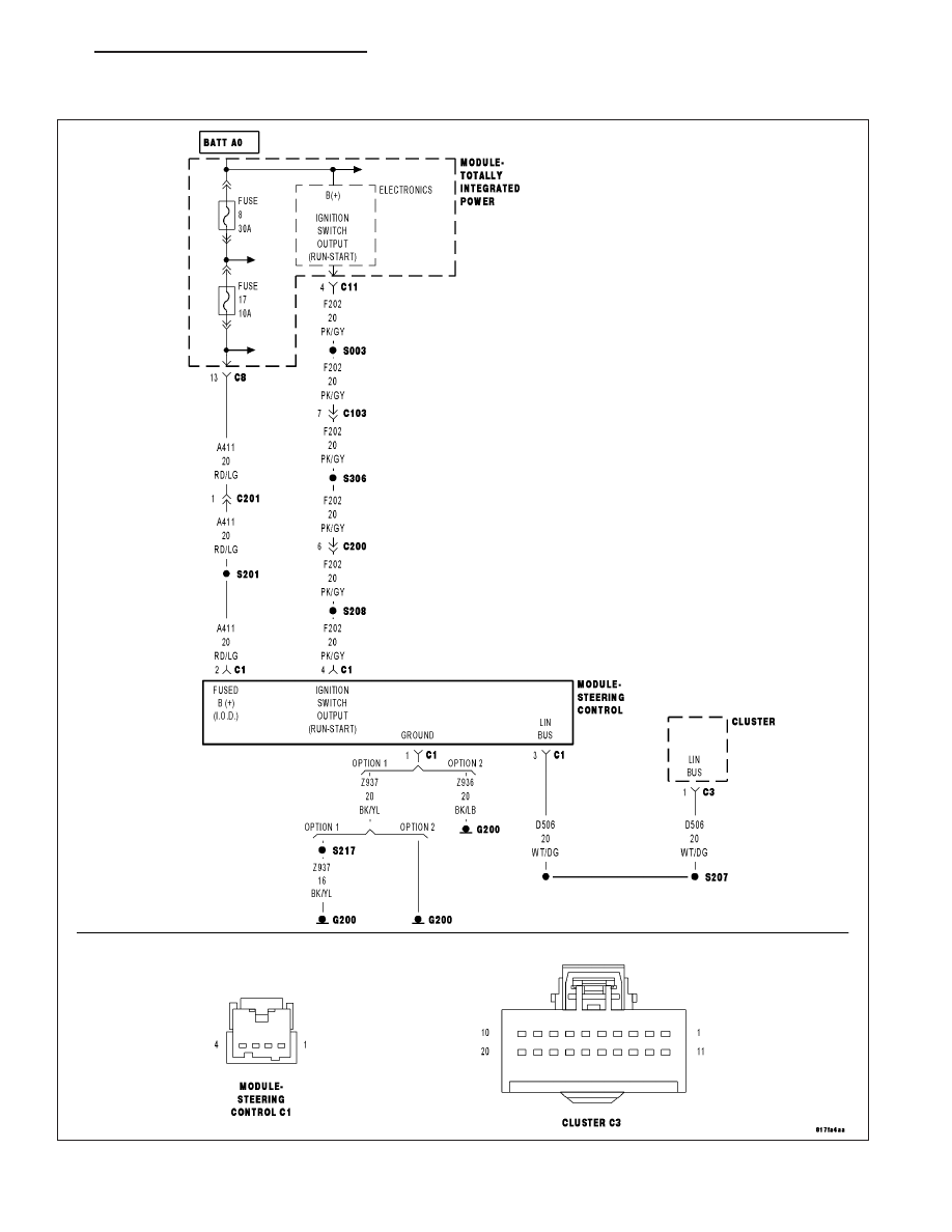
U0212-LOST COMMUNICATION WITH SCM
For a complete wiring diagram Refer to Section 8W.
PM
INSTRUMENT CLUSTER - ELECTRICAL DIAGNOSTICS
8J - 37
|
|
|
U0212-LOST COMMUNICATION WITH SCM For a complete wiring diagram Refer to Section 8W. PM INSTRUMENT CLUSTER - ELECTRICAL DIAGNOSTICS 8J - 37 |