Dodge Caliber. Manual - part 322


  Index      Dodge     Dodge Caliber - service repair manual 2007 year


Search            


Content   ..  320  321  322  323   ..


Dodge Caliber. Manual - part 322


CAPACITOR-IGNITION COIL

REMOVAL

1. Disconnect the negative battery cable.

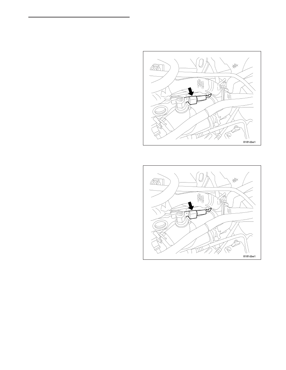
2. Remove the electrical connector from the ignition

coil capacitor.

3. Remove mounting bolt and remove capacitor.

INSTALLATION

1. Install coil capacitor and mounting bolt and tighten

to 12 N·m (105 in. lbs.).

2. Connect the electrical connector.

3. Connect the negative battery cable.

PM

IGNITION CONTROL- SERVICE INFORMATION

8I - 49

IGNITION SWITCH

REMOVAL

1. Access and remove the Steering Column Control

Module (SCCM) (3) from the steering column (2).
(Refer to 19 - STEERING/COLUMN/STEERING
COLUMN CONTROL MODULE - REMOVAL)

2. Remove the screw (1) fastening the SKREEM/

WCM (2) to the lock cylinder housing (3).

3. Unhook the SKREEM/WCM (2) retainer fingers

from the lock cylinder housing (3) and remove it.

8I - 50

IGNITION CONTROL- SERVICE INFORMATION

PM

4. Insert the key (2) and turn the key cylinder (3) to

the RUN position.

5. Insert an appropriate tool into the slot (1) formed

into the lock cylinder housing depressing the key
cylinder retaining tab.

6. Pull the key cylinder and key straight out of the

lock cylinder housing as one unit.

7. Using a Tamper-Proof Torx

T

Plus (five point) 30 bit,

remove the two screws (1) fastening the lock cylin-
der housing (2) to the column.

8. Remove the lock cylinder housing from the steering

column.

9. Remove the ignition switch (2) mounting screw (1).

PM

IGNITION CONTROL- SERVICE INFORMATION

8I - 51

10. Pull the switch (1) straight out and off the retain-

ing tabs (2) located on the lock cylinder housing.

INSTALLATION

NOTE: Ignition switch must be installed prior to
lock housing installation on column. Otherwise,
the tilt lever will obstruct installation of ignition
switch.

1. Ensure the ignition switch is in the RUN position

and the actuator shaft in the lock housing is in the
RUN position.

2. Align the ignition switch with the pin (3), actuator

shaft and retaining tabs (2) located on the lock cyl-
inder housing. Carefully install the switch, snapping
it into place over the retaining tabs.

8I - 52

IGNITION CONTROL- SERVICE INFORMATION

PM


Content   ..  320  321  322  323   ..