Dodge Caliber. Manual - part 318


  Index      Dodge     Dodge Caliber - service repair manual 2007 year


Search            


Content   ..  316  317  318  319   ..


Dodge Caliber. Manual - part 318


When Monitored:
With the ignition on.

Set Condition:
Over current condition detected on the Fused Ignition Switch Output (Run-Start) circuit.

Possible Causes

TERMINAL DAMAGE OR CORROSION

HIGH RESISTANCE ON THE (F200) FUSED IGNITION SWITCH OUTPUT (RUN-START) CIRCUIT

OCCUPANT RESTRAINT CONTROLLER (ORC)

TIPM

Diagnostic Test

1.

CHECK FOR ACTIVE DTC

With the scan tool, read the active DTC’s.

Cycle the ignition switch from off to on, leaving the ignition on for a minimum of 10 seconds.

With the scan tool, read the active DTC’s.

Does the scan tool display this DTC as active?

Yes

>> Go To 2

No

>> If the DTC is stored, check for an intermittent condition. Using the wiring diagram/schematic as a guide,

visually inspect the related wiring harness connectors. Look for broken, bent, pushed out, or corroded
terminals.

2.

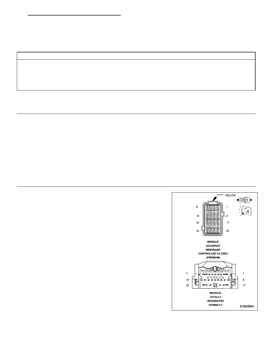
INSPECT THE TIPM AND ORC TERMINALS AND WIRE HARNESS FOR A CONDITION CAUSING HIGH
CIRCUIT RESISTANCE

WARNING: To avoid personal injury or death, turn the ignition off,
disconnect the battery and wait two minutes before proceeding.
Disconnect the TIPM C7 harness connector.

Disconnect the ORC harness connector.

Inspect the connector terminal for signs of corrosion build up and dam-
age.

Visually inspect the wiring harness for any chafed, pierced, pinched or
partially broken wires hidden in the wire insulation.

Were any of the above conditions found?

Yes

>> Repair as necessary.

Perform BODY VERIFICATION TEST VER 1. (Refer to 8 -
ELECTRICAL/ELECTRONIC

CONTROL

MODULES

-

STANDARD PROCEDURE)

No

>> Go To 3

PM

IGNITION SYSTEM - ELECTRICAL DIAGNOSTICS

8I - 33

3.

INSPECT THE (F202) FUSED IGNITION SWITCH OUTPUT (RUN-START) CIRCUIT FOR A CONDITION
CAUSING HIGH CIRCUIT RESISTANCE

Disconnect the TIPM C11 harness connector.

Inspect the connector terminal for signs of corrosion build up and damage.

Using the wiring diagrams, visually inspect the associated wiring harnesses and connectors for any chafed, pierced,
pinched or partially broken wires hidden in the wire insulation.

Were any of the above conditions found?

Yes

>> Repair as necessary.

Perform BODY VERIFICATION TEST VER 1. (Refer to 8 - ELECTRICAL/ELECTRONIC CONTROL
MODULES - STANDARD PROCEDURE)

No

>> Replace the TIPM in accordance with the service information.

Perform BODY VERIFICATION TEST VER 1. (Refer to 8 - ELECTRICAL/ELECTRONIC CONTROL
MODULES - STANDARD PROCEDURE)

8I - 34

IGNITION SYSTEM - ELECTRICAL DIAGNOSTICS

PM

B218C-IGNITION RUN CONTROL 2 CIRCUIT OVERCURRENT

For a complete wiring diagram Refer to Section 8W.

PM

IGNITION SYSTEM - ELECTRICAL DIAGNOSTICS

8I - 35

When Monitored:
With the ignition on.

Set Condition:
Over current condition detected on the (F937) Fused Ignition Switch Output (Run) circuit.

Possible Causes

TERMINAL DAMAGE OR CORROSION

HIGH RESISTANCE ON THE (F937) FUSED IGNITION SWITCH OUTPUT (RUN) CIRCUIT

HIGH RESISTANCE ON THE (F936) FUSED IGNITION SWITCH OUTPUT (RUN) CIRCUIT

HEATED SEAT MODULE

CABIN HEATER RELAYS 1 AND 2

TIPM

Diagnostic Test

1.

CHECK FOR ACTIVE DTC

With the scan tool, record and erase DTC’s.

Cycle the ignition switch from off to on, leaving the ignition off for a minimum of 30 seconds.

With the scan tool, read the active DTC’s.

Does the scan tool display this DTC as active?

Yes

>> Go To 2

No

>> If the DTC is stored, check for an intermittent condition. Using the wiring diagram/schematic as a guide,

visually inspect the related wiring harness connectors. Look for broken, bent, pushed out, or corroded
terminals.

2.

INSPECT THE TIPM AND HEATED SEAT MODULE TERMINALS AND WIRE HARNESS FOR A CONDITION
CAUSING HIGH CIRCUIT RESISTANCE

Turn the ignition off.

Disconnect the TIPM C8 harness connector.

Disconnect the Heated Seat Module harness connector.

Inspect the connector terminal for signs of corrosion build up and dam-
age.

Visually inspect the wiring harness for any chafed, pierced, pinched or
partially broken wires hidden in the wire insulation.

Were any of the above conditions found?

Yes

>> Repair as necessary.

Perform BODY VERIFICATION TEST VER 1. (Refer to 8 -
ELECTRICAL/ELECTRONIC

CONTROL

MODULES

-

STANDARD PROCEDURE)

No

>> Go To 3

8I - 36

IGNITION SYSTEM - ELECTRICAL DIAGNOSTICS

PM


Content   ..  316  317  318  319   ..