Dodge Caliber. Manual - part 316
3.
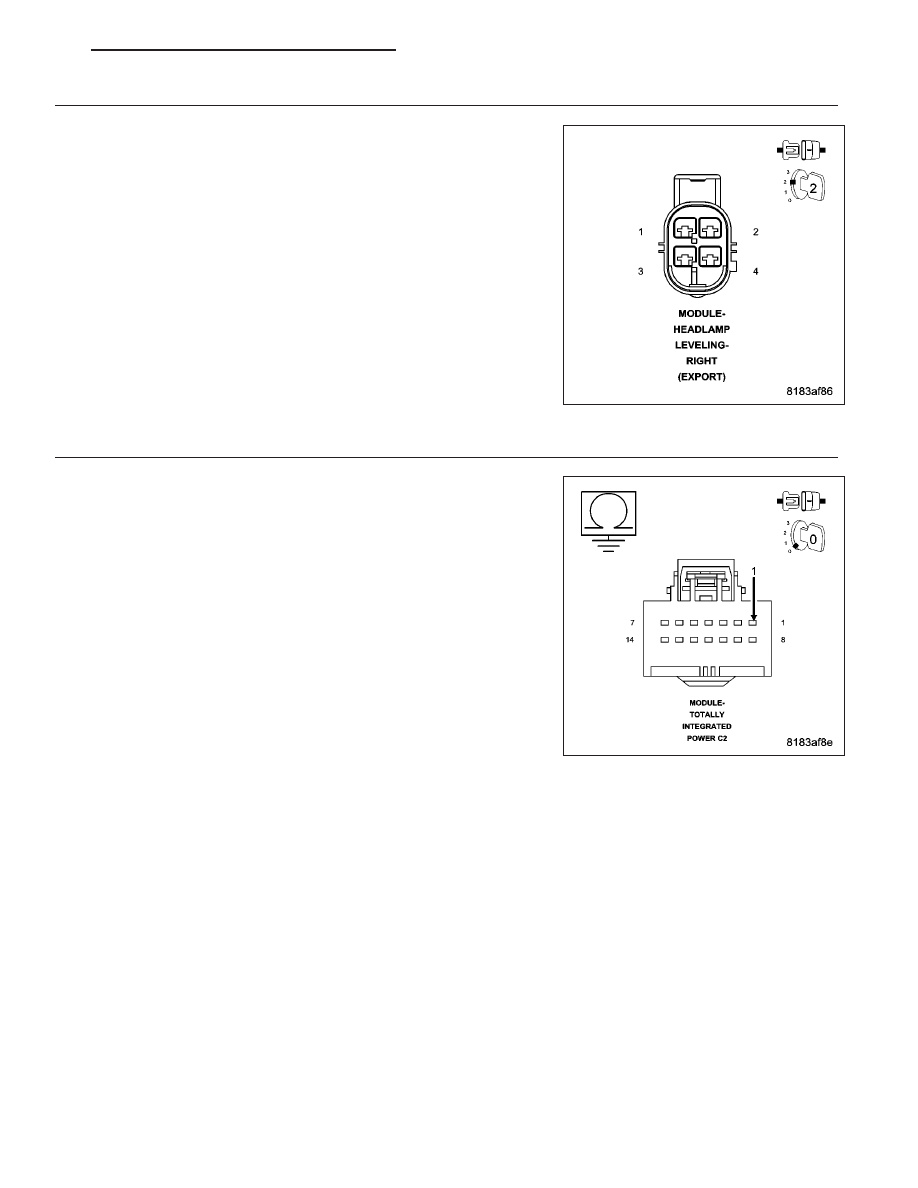
RIGHT HEADLAMP LEVELING MODULE INTERNAL SHORT
Turn the ignition off.
Disconnect the Right Headlamp Leveling Module harness connector.
Turn the ignition on.
With the scan tool, read DTCs.
Does the scan tool display B2184-IGNITION UNLOCK RUN/
START CONTROL CIRCUIT LOW?
Yes
>> Go To 4
No
>> Replace the Right Headlamp Leveling Module in accor-
dance with the service information.
Perform BODY VERIFICATION TEST VER 1 (Refer to 8 -
ELECTRICAL/ELECTRONIC
CONTROL
MODULES
-
STANDARD PROCEDURE)
4.
(F901) FUSED IGNITION SWITCH OUTPUT (UNLOCK-RUN-START) CIRCUIT SHORT TO GROUND
Turn the ignition off.
Disconnect the TIPM C2 harness connector.
Measure the resistance between ground and the (F901) Fused Ignition
Switch Output (Unlock-Run-Start) circuit.
Is the resistance below 10K ohms?
Yes
>> Repair the (F901) Fused Ignition Switch Output (Unlock-
Run-Start) circuit for a short to ground.
Perform BODY VERIFICATION TEST VER 1 (Refer to 8 -
ELECTRICAL/ELECTRONIC
CONTROL
MODULES
-
STANDARD PROCEDURE)
No
>> Replace the TIPM in accordance with the service informa-
tion.
Perform BODY VERIFICATION TEST VER 1 (Refer to 8 -
ELECTRICAL/ELECTRONIC
CONTROL
MODULES
-
STANDARD PROCEDURE)
PM
IGNITION SYSTEM - ELECTRICAL DIAGNOSTICS
8I - 25