Dodge Caliber. Manual - part 315
B2148-IGNITION RUN CONTROL 2 CIRCUIT LOW
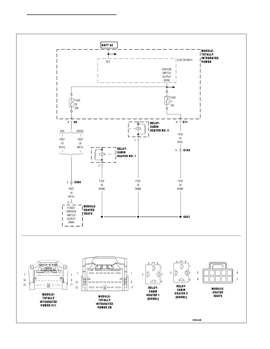
For a complete wiring diagram Refer to Section 8W.
PM
IGNITION SYSTEM - ELECTRICAL DIAGNOSTICS
8I - 21
|
|
|
B2148-IGNITION RUN CONTROL 2 CIRCUIT LOW For a complete wiring diagram Refer to Section 8W. PM IGNITION SYSTEM - ELECTRICAL DIAGNOSTICS 8I - 21 |