Dodge Caliber. Manual - part 287


  Index      Dodge     Dodge Caliber - service repair manual 2007 year


Search            


Content   ..  285  286  287  288   ..


Dodge Caliber. Manual - part 287


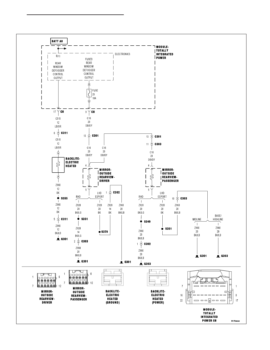
B106B–REAR DEFROST CONTROL CIRCUIT LOW (TIPM)

For a complete wiring diagram Refer to Section 8W.

PM

HEATED GLASS - ELECTRICAL DIAGNOSTICS

8G - 3

When Monitored:
With the ignition on. Battery voltage greater than 10.4 volts.

Set Condition:
A shorted low condition on the (C515) Rear Defogger Control Output or (C16) Fused Rear Defogger Control
Output circuit.

Possible Causes

(C515) REAR WINDOW DEFOGGER CONTROL OUTPUT CIRCUIT SHORTED TO GROUND

(C16) FUSED REAR WINDOW DEFOGGER CONTROL OUTPUT CIRCUIT PARTIAL SHORT TO GROUND (IF
EQUIPPED WITH HEATED MIRRORS)

HEATED MIRRORS (IF EQUIPPED)

TIPM

Diagnostic Test

1.

VERIFY DTC B106B–REAR DEFROST CONTROL CIRCUIT LOW IS ACTIVE

Ensure the Rear Defogger is switched off.

With the scan tool, erase TIPM DTCs.

Operate the Rear Defogger Switch several times.

With the scan tool, read TIPM DTCs.

Does the scan tool display active DTC B106B-REAR DEFROST CONTROL CIRCUIT LOW?

Yes

>> Go To 2

No

>> Check for an intermittent condition by inspecting the related wiring harness for chafed, pierced, pinched,

and partially broken wires. Also, inspect the related connectors for broken, bent, corroded, or contami-
nated terminals.

Perform BODY VERIFICATION TEST - VER 1. (Refer to 8 - ELECTRICAL/ELECTRONIC CONTROL
MODULES - STANDARD PROCEDURE)

2.

INSPECT (C515) REAR WINDOW DEFOGGER CONTROL OUTPUT CIRCUIT AT REAR WINDOW GRID

Inspect (C515) Rear Window Defogger Control Output wiring at rear window grid. If necessary remove trim around
rear window.

Check for a chafed, pierced or pinched wire. Also look for a metal object that may cause a short to ground condition
at the grid.

Were there any problems found?

Yes

>> Repair as necessary.

Perform the BODY VERIFICATION TEST – VER 1 (Refer to 8 - ELECTRICAL/ELECTRONIC CON-
TROL MODULES - STANDARD PROCEDURE)

No

>> Go To 3

3.

VEHICLE EQUIPPED WITH HEATED MIRRORS

Is this vehicle equipped with heated mirrors?

Yes

>> Go To 4

No

>> Go To 6

8G - 4

HEATED GLASS - ELECTRICAL DIAGNOSTICS

PM

4.

DISCONNECT MIRROR AND RE-CHECK DTC

NOTE: For this step disconnect each outside rearview mirror one at a time and re–check DTC’s.
With the scan tool, erase TIPM DTCs.

Operate the Rear Defogger Switch several times.

With the scan tool, read TIPM DTCs.

Does the scan tool display active DTC B106B-REAR DEFROST CONTROL CIRCUIT LOW?

Yes

>> Go To 5

No

>> Inspect mirror pigtail wiring, if the wiring is OK replace mirror as necessary. Perform the BODY VERI-

FICATION TEST – VER 1 (Refer to 8 - ELECTRICAL/ELECTRONIC CONTROL MODULES - STAN-
DARD PROCEDURE)

5.

(C16) FUSED REAR WINDOW DEFOGGER CONTROL OUTPUT CIRCUIT SHORTED TO GROUND

Turn the ignition off.

Both outside review mirrors should be disconnected at this time.

Disconnect the TIPM C8 harness connector.

Measure the resistance between ground and the (C16) Fused Rear
Window Defogger Control Output circuit at the TIPM C8 harness con-
nector.

Is the resistance below 100 ohms?

Yes

>> Repair the short to ground in the (C16) Fused Rear Window

Defogger Control Output circuit.

Perform the BODY VERIFICATION TEST – VER 1. (Refer
to 8 - ELECTRICAL/ELECTRONIC CONTROL MODULES -
STANDARD PROCEDURE)

No

>> Go To 6

6.

(C515) REAR WINDOW DEFOGGER CONTROL OUTPUT CIRCUIT SHORTED TO GROUND

Turn the ignition off.

Disconnect the Electric Heated Backlite (Power) 1-way connector.

Disconnect the TIPM C8 harness connector.

Measure the resistance between ground and the (C515) Rear Window
Defogger Control Output circuit at the TIPM C8 harness connector.

Is the resistance below 100 ohms?

Yes

>> Repair the short to ground in the (C515) Rear Window

Defogger Control Output circuit.

Perform the BODY VERIFICATION TEST – VER 1. (Refer
to 8 - ELECTRICAL/ELECTRONIC CONTROL MODULES -
STANDARD PROCEDURE)

No

>> Go To 7

PM

HEATED GLASS - ELECTRICAL DIAGNOSTICS

8G - 5

7.

TOTALLY INTEGRATED POWER MODULE

NOTE: Before continuing, check the TIPM harness connector terminals for corrosion, damage, or terminal
push out. Repair as necessary.
Using the schematics as a guide, inspect the wire harness and connectors.

Pay particular attention to all Power and Ground circuits.

Were any problems found?

Yes

>> Repair as necessary.

Perform the BODY VERIFICATION TEST – VER 1. (Refer to 8 - ELECTRICAL/ELECTRONIC CON-
TROL MODULES - STANDARD PROCEDURE)

No

>> Replace the Totally Integrated Power Module in accordance with the service information.

Perform the BODY VERIFICATION TEST – VER 1. (Refer to 8 - ELECTRICAL/ELECTRONIC CON-
TROL MODULES - STANDARD PROCEDURE)

8G - 6

HEATED GLASS - ELECTRICAL DIAGNOSTICS

PM


Content   ..  285  286  287  288   ..