Dodge Caliber. Manual - part 279


  Index      Dodge     Dodge Caliber - service repair manual 2007 year


Search            


Content   ..  277  278  279  280   ..


Dodge Caliber. Manual - part 279


BATTERY HOLDDOWN

REMOVAL

1. Disconnect and isolate the battery negative cable.

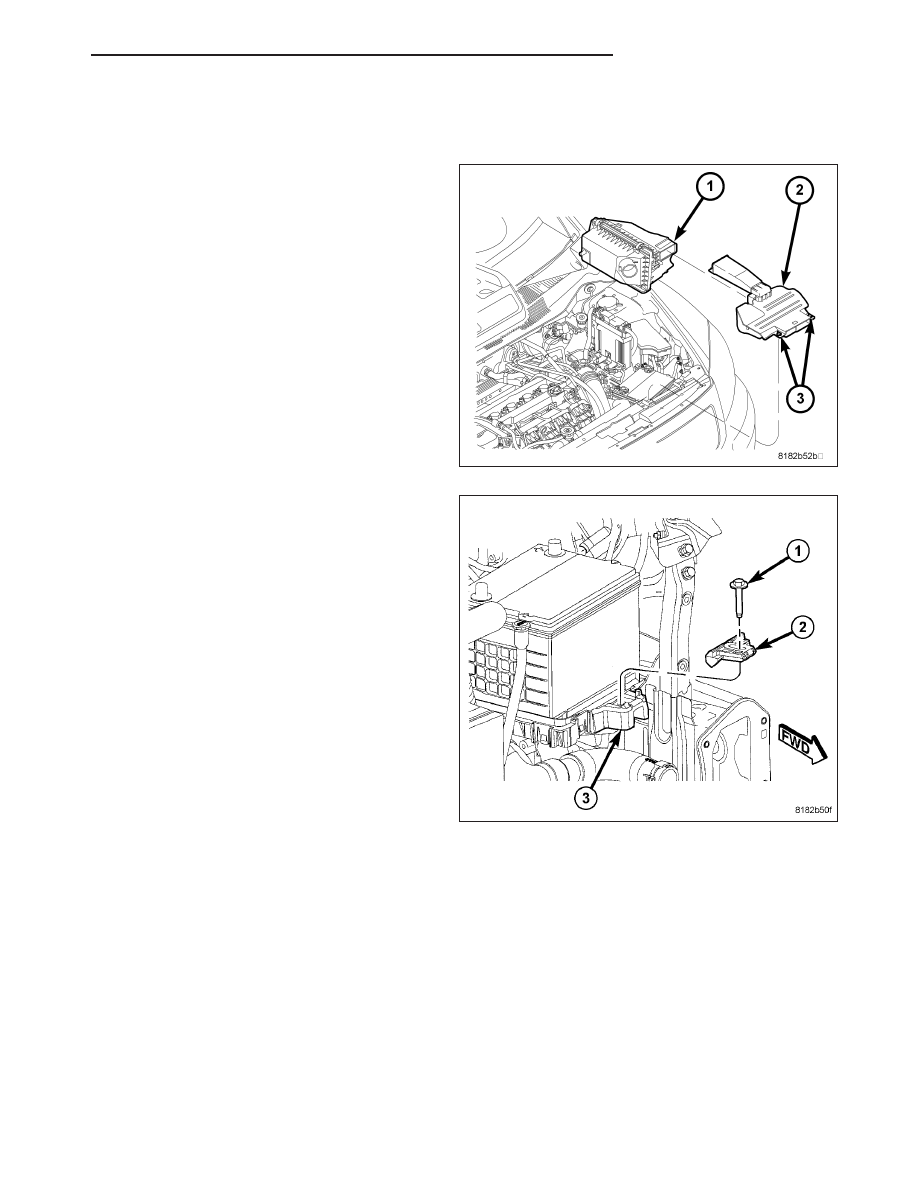
2. Rotate the two retaining clips (3) and remove the

air cleaner fresh air duct (2).

3. Remove the battery hold down retaining bolt (1).

4. Remove the battery hold down (2) from the vehicle.

PM

BATTERY SYSTEM

8F - 21

INSTALLATION

1. Install the battery hold down (2) into the vehicle.

2. Install the battery hold down retaining bolt (1).

Tighten the bolt to 7 N·m (62 in. lbs.).

3. Install the air cleaner fresh air duct (2) and secure

in place by rotating the two retaining clips (3).

4. Connect the battery negative cable.

8F - 22

BATTERY SYSTEM

PM

BATTERY CABLES

DESCRIPTION

The battery cables are large gauge, stranded copper wires sheathed within a heavy plastic or synthetic rubber insu-
lating jacket. The wire used in the battery cables combines excellent flexibility and reliability with high electrical cur-
rent carrying capacity. The battery cables feature a clamping type female battery terminal made of stamped sheet
metal that is die cast onto one end of the battery cable wire. A pinch-bolt and nut are installed at the open end of
the female battery terminal clamp. Large eyelet type terminals are crimped onto the opposite end of the battery
cable wire and then soldered. The battery positive cable wires feature a larger female battery terminal clamp to
allow connection to the larger battery positive terminal post. The battery negative cable wires have a smaller female
battery terminal clamp.

Both the battery positive and negative cables are available for service replacement only as a unit with the battery
wire harness, which may include portions of the wiring circuits for the generator and other components on some
vehicles.

OPERATION

The battery cables connect the battery terminal posts to the vehicle electrical system. These cables also provide a
path back to the battery for electrical current generated by the charging system for restoring the voltage potential of
the battery. The female battery terminal clamps on the ends of the battery cable wires provide a strong and reliable
connection of the battery cable to the battery terminal posts. The terminal pinch bolts allow the female terminal
clamps to be tightened around the male terminal posts on the top of the battery. The eyelet terminals secured to the
opposite ends of the battery cable wires from the female battery terminal clamps provide secure and reliable con-
nection of the battery cables to the vehicle electrical system.

One wire has an eyelet terminal that connects the battery positive cable to the B(+) terminal stud of the Totally
Integrated Power Module (TIPM), and the other wire has an eyelet terminal that connects the battery positive cable
to the B(+) terminal stud of the engine starter motor solenoid. The battery negative cable terminal clamp has one
wire as an eyelet terminal that connects the battery negative cable to the vehicle powertrain through a ground con-
nection, typically on the engine cylinder block.

DIAGNOSIS AND TESTING

BATTERY CABLES

A voltage drop test will determine if there is excessive resistance in the battery cable terminal connections or the
battery cable. If excessive resistance is found in the battery cable connections, the connection point should be dis-
assembled, cleaned of all corrosion or foreign material, then reassembled. Following reassembly, check the voltage
drop for the battery cable connection and the battery cable again to confirm repair.

When performing the voltage drop test, it is important to remember that the voltage drop is giving an indication of
the resistance between the two points at which the voltmeter probes are attached. EXAMPLE: When testing the
resistance of the battery positive cable, touch the voltmeter leads to the battery positive cable terminal clamp and to
the battery positive cable eyelet terminal at the starter solenoid B(+) terminal stud. If you probe the battery positive
terminal post and the battery positive cable eyelet terminal at the starter solenoid B(+) terminal stud, you are read-
ing the combined voltage drop in the battery positive cable terminal clamp-to-terminal post connection and the bat-
tery positive cable.

VOLTAGE DROP TEST

The following operation will require a voltmeter accurate to 1/10 (0.10) volt. Before performing this test, be certain
that the following procedures are accomplished:

The battery is fully-charged and load tested. Refer to Standard Procedures for the proper battery charging and
load test procedures.

Fully engage the parking brake.

If the vehicle is equipped with an automatic transmission, place the gearshift selector lever in the Park position.
If the vehicle is equipped with a manual transmission, place the gearshift selector lever in the Neutral position
and block the clutch pedal in the fully depressed position.

Verify that all lamps and accessories are turned off.

PM

BATTERY SYSTEM

8F - 23

To prevent the engine from starting, remove the Automatic Shut Down (ASD) relay. The ASD relay is located
in the Totally Integrated Power Module (TIPM), in the engine compartment. See the fuse and relay layout label
affixed to the underside of the TIPM cover for ASD relay identification and location.

1. Connect the positive lead of the voltmeter (1) to the

battery (2) negative terminal post. Connect the
negative lead of the voltmeter (1) to the battery (2)
negative cable terminal clamp. Rotate and hold the
ignition switch in the Start position. Observe the
voltmeter. If voltage is detected, correct the poor
connection between the battery negative cable ter-
minal clamp and the battery negative terminal post.

2. Connect the positive lead of the voltmeter (1) to the

battery (2) positive terminal post. Connect the neg-
ative lead of the voltmeter (1) to the battery (2)
positive cable terminal clamp. Rotate and hold the
ignition switch in the Start position. Observe the
voltmeter. If voltage is detected, correct the poor
connection between the battery positive cable ter-
minal clamp and the battery positive terminal post.

3. Connect the voltmeter (2) to measure between the

battery positive cable terminal clamp (1) and the
starter solenoid B(+) terminal stud (3). Rotate and
hold the ignition switch in the Start position.
Observe the voltmeter. If the reading is above 0.2
volt, clean and tighten the battery positive cable
eyelet terminal connection at the starter solenoid
B(+) terminal stud. Repeat the test. If the reading is
still above 0.2 volt, replace the faulty battery posi-
tive cable.

8F - 24

BATTERY SYSTEM

PM


Content   ..  277  278  279  280   ..