Dodge Caliber. Manual - part 257


  Index      Dodge     Dodge Caliber - service repair manual 2007 year


Search            


Content   ..  255  256  257  258   ..


Dodge Caliber. Manual - part 257


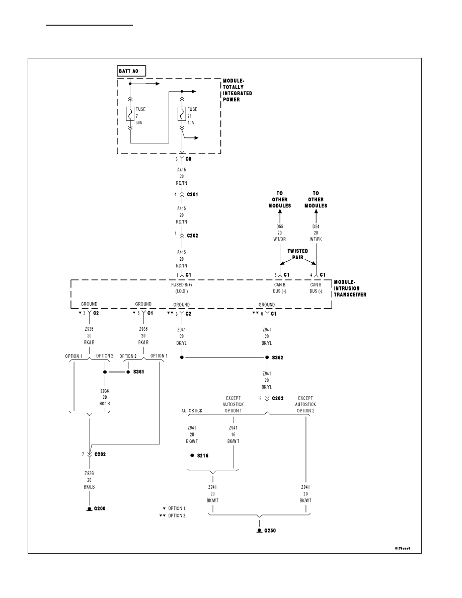
*NO RESPONSE FROM ITM (INTRUSION TRANSCEIVER MODULE)

For a complete wiring diagram Refer to Section 8W.

PM

ELECTRONIC CONTROL MODULES - ELECTRICAL DIAGNOSTICS

8E - 139

Possible Causes

(A415) FUSED B (+) CIRCUIT OPEN OR SHORTED

(Z936) (Z941) GROUND CIRCUITS OPEN

(D55) AND (D54) CAN B BUS CIRCUITS OPEN

INTRUSION TRANSCEIVER MODULE

Diagnostic Test

1.

TEST FOR INTERMITTENT CONDITION

Turn the ignition on.

NOTE: Ensure the IOD fuse is installed and battery voltage is between 10.0 and 16.0 volts.
With the scan tool, select ECU View.

NOTE: A red X will be next to the module that is not communicating, indicating that the module is not active
on the Bus network. A green check indicates that the module is active on the Bus network.

Does the scan tool display a red X next to the module?

Yes

>> Go To 2

No

>> The no response condition is not present at this time. Using the wiring diagram/schematic as a guide,

inspect the wiring for chafed, pierced, pinched, and partially broken wires and the wiring harness con-
nectors for broken, bent, pushed out, and corroded terminals.

2.

(A415) FUSED B(+) CIRCUIT OPEN OR SHORTED

Turn the ignition off.

Disconnect the Intrusion Transceiver Module C1 and C2 harness con-
nectors.

Using a 12-volt test light connected to ground, check the (A415) Fused
B(+) circuit.

Does the test light illuminate brightly?

Yes

>> Go To 3

No

>> Repair the (A415) Fused B(+) circuit for an open or short.

Perform the BODY VERIFICATION TEST – VER 1. (Refer
to 8 - ELECTRICAL/ELECTRONIC CONTROL MODULES -
STANDARD PROCEDURE).

8E - 140

ELECTRONIC CONTROL MODULES - ELECTRICAL DIAGNOSTICS

PM

3.

(Z936) (Z937) GROUND CIRCUITS OPEN

Using a 12-volt test light connected to 12-volts, check the (Z936) and
(Z941) ground circuits.

Does the test light illuminate brightly for each circuit?

Yes

>> Go To 4

No

>> Repair the (Z936) or (Z941) ground circuit for an open.

Perform the BODY VERIFICATION TEST – VER 1. (Refer
to 8 - ELECTRICAL/ELECTRONIC CONTROL MODULES -
STANDARD PROCEDURE).

4.

(D55) AND (D54) CAN B BUS CIRCUITS OPEN

NOTE: One open circuit will not cause this condition.
Measure the voltage between the (D54) CAN B Bus (-) circuit and
ground.

Measure the voltage between the (D55) CAN B Bus (+) circuit and
ground.

Is there any voltage present on either circuit?

Yes

>> Replace the Intrusion Transceiver Module in accordance

with the service information.

Perform the BODY VERIFICATION TEST – VER 1. (Refer
to 8 - ELECTRICAL/ELECTRONIC CONTROL MODULES -
STANDARD PROCEDURE).

No

>> Repair the (D55) and (D54) CAN B Bus circuits for an open.

Inspect the connector for damage.

Perform the BODY VERIFICATION TEST – VER 1. (Refer
to 8 - ELECTRICAL/ELECTRONIC CONTROL MODULES -
STANDARD PROCEDURE).

PM

ELECTRONIC CONTROL MODULES - ELECTRICAL DIAGNOSTICS

8E - 141

*NO RESPONSE FROM OCM (OCCUPANT CLASSIFICATION MODULE)

For a complete wiring diagram Refer to Section 8W.

8E - 142

ELECTRONIC CONTROL MODULES - ELECTRICAL DIAGNOSTICS

PM


Content   ..  255  256  257  258   ..