Dodge Caliber. Manual - part 255
3.
(Z936) (Z937) GROUND CIRCUITS OPEN
Using a 12-volt test light connected to 12-volts, check each (Z936) and
(Z937) ground circuit.
Does the test light illuminate brightly for each circuit?
Yes
>> Go To 4
No
>> Repair the (Z936) or (Z937) ground circuit for an open.
Perform the BODY VERIFICATION TEST – VER 1. (Refer
to 8 - ELECTRICAL/ELECTRONIC CONTROL MODULES -
STANDARD PROCEDURE).
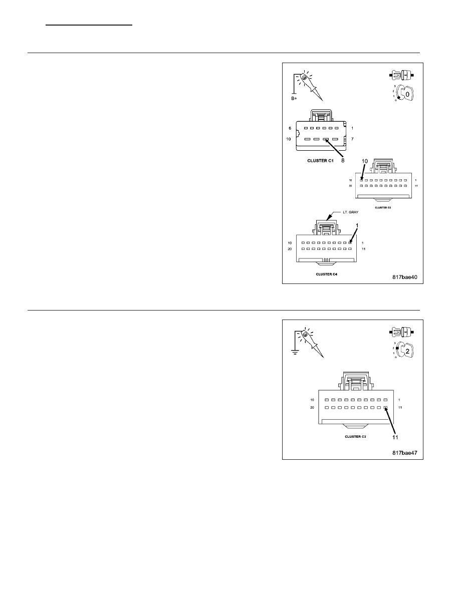
4.
(F202) IGNITION SWITCH OUTPUT CIRCUIT OPEN OR SHORTED
Turn the ignition on.
Using a 12-volt test light connected to ground, check the (F202) Ignition
Switch Output circuit.
Does the test light illuminate brightly?
Yes
>> Go To 5
No
>> Repair the (F202) Ignition Switch Output circuit for an open
or short.
Perform the BODY VERIFICATION TEST – VER 1. (Refer
to 8 - ELECTRICAL/ELECTRONIC CONTROL MODULES -
STANDARD PROCEDURE).
PM
ELECTRONIC CONTROL MODULES - ELECTRICAL DIAGNOSTICS
8E - 131