Dodge Caliber. Manual - part 229


  Index      Dodge     Dodge Caliber - service repair manual 2007 year


Search            


Content   ..  227  228  229  230   ..


Dodge Caliber. Manual - part 229


When Monitored:
With the ignition on and battery voltage between 10 and 16 volts.

Set Condition:
The TIPM detects the (D54) CAN B Bus (-) circuit is open.

Possible Causes

CAN B BUS TERMINAL PUSH OUT

SPREAD CAN B BUS TERMINAL

(D54) CAN B BUS (-) CIRCUIT OPEN

INTERNAL OPEN IN A CAN B BUS MODULE

Diagnostic Test

1.

TEST FOR INTERMITTENT CONDITION

Turn the ignition on.

With the scan tool, record and erase TIPM DTC’s

Cycle the ignition from on to off 3 times.

Turn the ignition on.

With the scan tool, read active TIPM DTC’s.

Does the scan tool display this DTC as active?

Yes

>> Go To 2

No

>> The conditions that caused this code to set are not present at this time. Using the wiring diagram/sche-

matic as a guide, inspect the wiring and connectors.

2.

ATTEMPT TO ISOLATE THE OPEN CONDITION

Turn the ignition on.

With the scan tool select ECU View.

Verify that all CAN B Bus modules are communicating with the scan
tool.

NOTE: A red X will be next to a module that is not communicating,
indicating that the module is not active on the Bus network. A
green check indicates that the module is active on the Bus net-
work.

NOTE: If any module is not communicating, perform the appropri-
ate no response test procedure before proceeding.
Turn the ignition off.

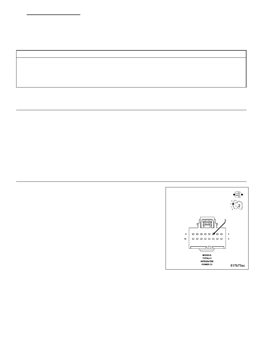
Gain access to the Totally Integrated Power Module C3 harness con-
nector, but do not disconnect.

Using a fused jumper wire, connect one end to ground and with the
other end backprobe the CAN B Bus (+) circuit at the TIPM C3 harness
connector.

Turn the ignition on.

With the scan tool monitor the ECU View screen and document all modules that display a red X.

Are there any red X’s displayed next to any CAN B Bus modules?

Yes

>> Go To 3

No

>> Check backprobe connection to ground, make sure it is proper. The CAN B Bus open DTC may no

longer be active, it may be stored. Check all module connections.

Perform the BODY VERIFICATION TEST – VER 1. (Refer to 8 - ELECTRICAL/ELECTRONIC CON-
TROL MODULES - STANDARD PROCEDURE).

PM

ELECTRONIC CONTROL MODULES - ELECTRICAL DIAGNOSTICS

8E - 27

3.

ATTEMPT TO ISOLATE THE OPEN CONDITION — MULTIPLE RED X’S

With the scan tool continue monitoring the ECU View screen.

Are there multiple red X’s displayed next to CAN B Bus modules?

Yes

>> The most likely cause of this condition is an open CAN B Bus (-) circuit between a common CAN B Bus

splice and the modules that display the red X next to them. Use the wiring diagrams to help you deter-
mine where the open condition exists.

Perform the BODY VERIFICATION TEST – VER 1. (Refer to 8 - ELECTRICAL/ELECTRONIC CON-
TROL MODULES - STANDARD PROCEDURE).

No

>> Go To 4

4.

(D54) CAN B BUS (-) CIRCUIT OPEN — SINGLE RED X

Turn the ignition off.

Disconnect the module that has the red X displayed next to it.

Turn the ignition on.

Measure the voltage between the (D54) CAN B Bus (-) circuit and ground.

Is there any voltage present?

Yes

>> Inspect the connector and terminal for damage, inspect for spread terminals, or pushed out terminals. If

ok, replace the module that displayed the red X next to it in accordance with the service information.

Perform BODY VERIFICATION TEST – VER 1. (Refer to 8 - ELECTRICAL/ELECTRONIC CONTROL
MODULES - STANDARD PROCEDURE).

No

>> Repair the (D54) CAN B Bus (-) circuit for an open between the next common splice and the module

that has the red X displayed next to it. Use the wiring diagrams to help you determine where the open
condition exists.

Perform the BODY VERIFICATION TEST – VER 1. (Refer to 8 - ELECTRICAL/ELECTRONIC CON-
TROL MODULES - STANDARD PROCEDURE).

8E - 28

ELECTRONIC CONTROL MODULES - ELECTRICAL DIAGNOSTICS

PM

U0025-CAN B BUS (-) CIRCUIT LOW

For a complete wiring diagram Refer to Section 8W.

PM

ELECTRONIC CONTROL MODULES - ELECTRICAL DIAGNOSTICS

8E - 29

When Monitored:
Continuously.

Set Condition:
The TIPM detects the (D54) CAN B Bus (-) circuit is shorted to ground.

Possible Causes

(D54) CAN B BUS (-) CIRCUIT SHORTED TO GROUND OR TO (D55) CAN B BUS (+) CIRCUIT

ANY CAN B BUS MODULE

Diagnostic Test

1.

TEST FOR INTERMITTENT CONDITION

Turn the ignition on.

With the scan tool, record and erase TIPM DTC’s.

Cycle the ignition from on to off 3 times.

Turn the ignition on.

With the scan tool, read active TIPM DTC’s.

Does the scan tool display this DTC as active?

Yes

>> Go To 2

No

>> The conditions that caused this code to set are not present at this time. Using the wiring diagram/sche-

matic as a guide, inspect the wiring and connectors.

2.

CHECK THE (D54) CAN B BUS (-) CIRCUIT FOR A SHORT TO GROUND

Turn the ignition off.

Disconnect the Totally Integrated Power Module C3 harness connector.

Measure the resistance between ground and the (D54) CAN B Bus (-)
circuit.

Is resistance below 1000.0 ohms?

Yes

>> Go To 3

No

>> Go To 4

8E - 30

ELECTRONIC CONTROL MODULES - ELECTRICAL DIAGNOSTICS

PM


Content   ..  227  228  229  230   ..