Dodge Caliber. Manual - part 228
U0023-CAN B BUS (+) CIRCUIT HIGH
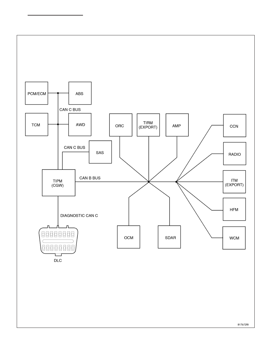
For a complete wiring diagram Refer to Section 8W.
PM
ELECTRONIC CONTROL MODULES - ELECTRICAL DIAGNOSTICS
8E - 23
|
|
|
U0023-CAN B BUS (+) CIRCUIT HIGH For a complete wiring diagram Refer to Section 8W. PM ELECTRONIC CONTROL MODULES - ELECTRICAL DIAGNOSTICS 8E - 23 |