Dodge Caliber. Manual - part 218


  Index      Dodge     Dodge Caliber - service repair manual 2007 year


Search            


Content   ..  216  217  218  219   ..


Dodge Caliber. Manual - part 218


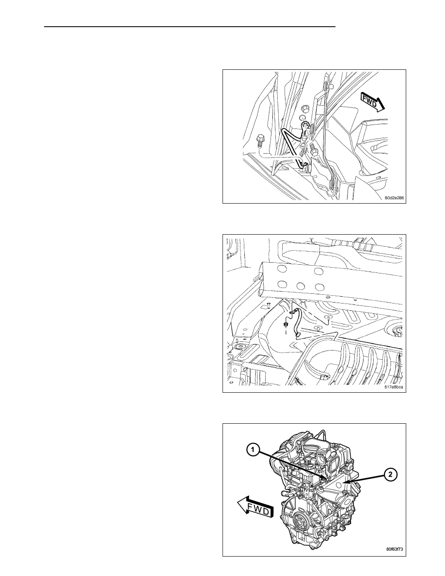
HOOD HINGE GROUND STRAP

1. Install strap and bolt to fender. Tighten bolt to 4

N·m (35 in. lbs.).

2. Install strap and bolt to hood. Tighten bolt to 4 N·m

(35 in. lbs.).

3. Connect battery negative cable.

MUFFLER GROUND STRAP

1. Install strap and bolt to rear floor pan. Tighten bolt

to 8 N·m (75 in. lbs.).

2. Install strap and bolt to muffler. Tighten bolt to 8

N·m (75 in. lbs.).

3. Connect battery negative cable.

RADIO NOISE SUPPRESSION CAPACITOR

1. Install capacitor and bolt.

2. Connect electrical harness connector to capacitor.

3. Connect battery negative cable.

PM

AUDIO

8A - 145

STRUT BRACKET TO BODY GROUND STRAP

1. Install strap to frame rail.

CAUTION: Ensure that ground strap does not
come in contact with brake hose. Damage to brake
hose can result.

2. Install strap and bolt to strut. Tighten bolt to 12 N·m

(105 in. lbs.).

3. Connect battery negative cable.

8A - 146

AUDIO

PM

RECEIVER-SATELLITE

DESCRIPTION

The satellite receiver module is located behind the spare tire. It is mounted to a bracket which is fastened to the
trunk floor sheet metal.

OPERATION

The satellite receiver module receives signals from the roof mounted antenna and processes this information before
it is sent to the radio. The module operates on both battery and accessory feed circuits and will operate with the
ignition key in the RUN or ACCESSORY position only.

REMOVAL

NOTE:
If the owner’s satellite service was active before the satellite receiver module was replaced the new satellite
receiver module will have to be activated. The existing satellite receiver module will have to be deactivated
before the replacement satellite receiver module can be activated.
To activate Sirius satellite radio service, call Sirius at their toll-free number. Please have the following infor-
mation available when activating a system:

Electronic Serial Number / Sirius Identification Number (ESN/SID) of the unit to be replaced

ESN/SID of the replacement receiver

Vehicle Owner’s name and address

VIN
The ESN/SID number can be obtained through the radio display by following the steps in the satellite
radio owners manual.
The vehicle must be outside with the audio system powered on, in the satellite radio mode, to receive the
activation signal.

1. Disconnect and isolate the battery negative cable.

2. Remove the left rear quarter trim panel (Refer to

23

-

BODY/INTERIOR/LEFT

QUARTER

TRIM

PANEL - REMOVAL).

3. Remove the mounting bracket fasteners.

4. Disconnect the wire harness connectors.

5. Remove the module from the mounting bracket.

PM

AUDIO

8A - 147

INSTALLATION

NOTE:
If the owner’s satellite service was active before the satellite receiver module was replaced the new satellite
receiver module will have to be activated. The existing satellite receiver module will have to be deactivated
before the replacement satellite receiver module can be activated.
To activate Sirius satellite radio service, call Sirius at their toll-free number. Please have the following infor-
mation available when activating a system:

Electronic Serial Number / Sirius Identification Number (ESN/SID) of the unit to be replaced

ESN/SID of the replacement receiver

Vehicle Owner’s name and address

VIN
The ESN/SID number can be obtained through the radio display by following the steps in the satellite
radio owners manual.
The vehicle must be outside with the audio system powered on, in the satellite radio mode, to receive the
activation signal.

1. Position the module to the mounting bracket.

2. Connect wire harness connectors.

3. Install mounting bracket and fasteners.

4. Install the left rear quarter trim panel (Refer to 23 -

BODY/INTERIOR/LEFT QUARTER TRIM PANEL -
INSTALLATION).

5. Connect the battery negative cable.

8A - 148

AUDIO

PM


Content   ..  216  217  218  219   ..