Dodge Caliber. Manual - part 151
If the amber ABS warning indicator is on, road test the vehicle as described below. While only the amber ABS
warning indicator is on, the ABS is not functional. The ability to stop the car using the base brake system should not
be affected.
6. Turn the key to the OFF position and then back to the ON position. Note whether the amber ABS warning indi-
cator lamp continues to stay on.
7. If the amber ABS warning indicator lamp stays on, shift into gear and drive the car to a speed of approximately
15 mph (25 km/h) to complete the ABS Start-Up and Drive-Off Cycles (Refer to 5 - BRAKES - ABS - OPERA-
TION). If at this time the amber ABS warning indicator lamp stays on, refer to the appropriate diagnostic infor-
mation.
8. If the amber ABS warning indicator lamp goes out at any time, drive the vehicle a short distance. Accelerate the
vehicle to a speed of at least 64 km/h (40 mph). Bring the vehicle to a complete stop, braking hard enough to
cause the ABS to cycle. Repeat this action several times. Using the scan tool, read and record any Diagnostic
Trouble Codes (DTCs). If any DTCs are present, refer to the appropriate diagnostic information.
STANDARD PROCEDURE
ANTILOCK BRAKE SYSTEM BLEEDING
The base brake’s hydraulic system must be bled anytime air enters the hydraulic system. The ABS must always be
bled anytime it is suspected that the HCU has ingested air.
Brake systems with ABS must be bled as two independent braking systems. The non-ABS portion of the brake
system with ABS is to be bled the same as any non-ABS system.
The ABS portion of the brake system must be bled separately. Use the following procedure to properly bleed the
brake hydraulic system including the ABS.
NOTE: During the brake bleeding procedure, be sure the brake fluid level remains close to the FULL level in
the master cylinder fluid reservoir. Check the fluid level periodically during the bleeding procedure and add
Mopar
T
DOT 3 brake fluid as required.
BLEEDING
When bleeding the ABS system, the following bleeding sequence must be followed to insure complete and adequate
bleeding.
1. Make sure all hydraulic fluid lines are installed and properly torqued.
2. Connect the scan tool to the diagnostics connector. The diagnostic connector is located under the lower steering
column cover to the left of the steering column.
3. Using the scan tool, check to make sure the ABM does not have any fault codes stored. If it does, clear them.
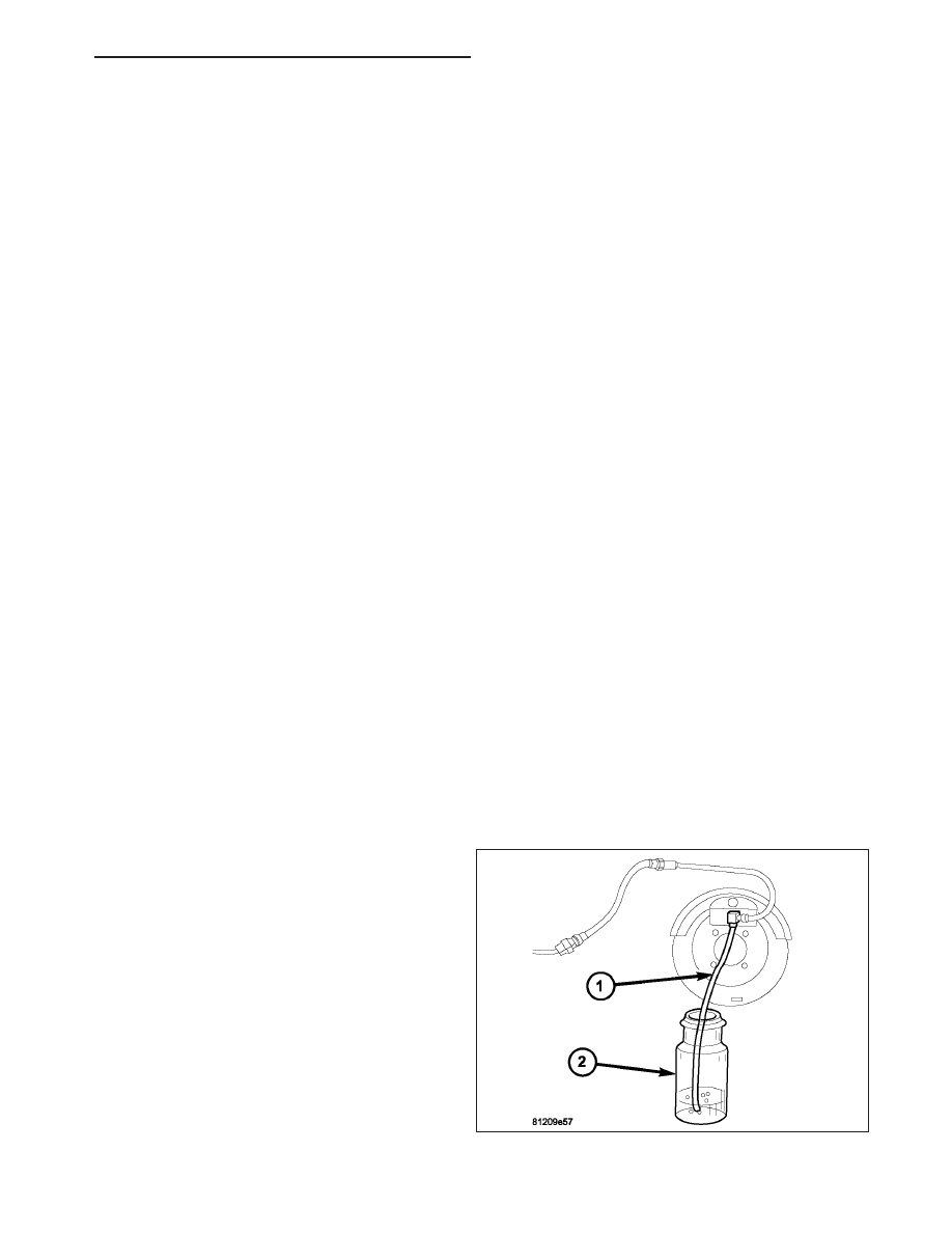
WARNING: When bleeding the brake system wear
safety glasses. A clear bleed tube (1) must be
attached to the bleeder screws and submerged in
a clear container filled part way with clean brake
fluid (2). Direct the flow of brake fluid away from
yourself and the painted surfaces of the vehicle.
Brake fluid at high pressure may come out of the
bleeder screws when opened.
PM
BRAKES - ABS SERVICE INFORMATION
5 - 305