Content .. 1421 1422 1423 1424 ..
Dodge Caliber. Manual - part 1423
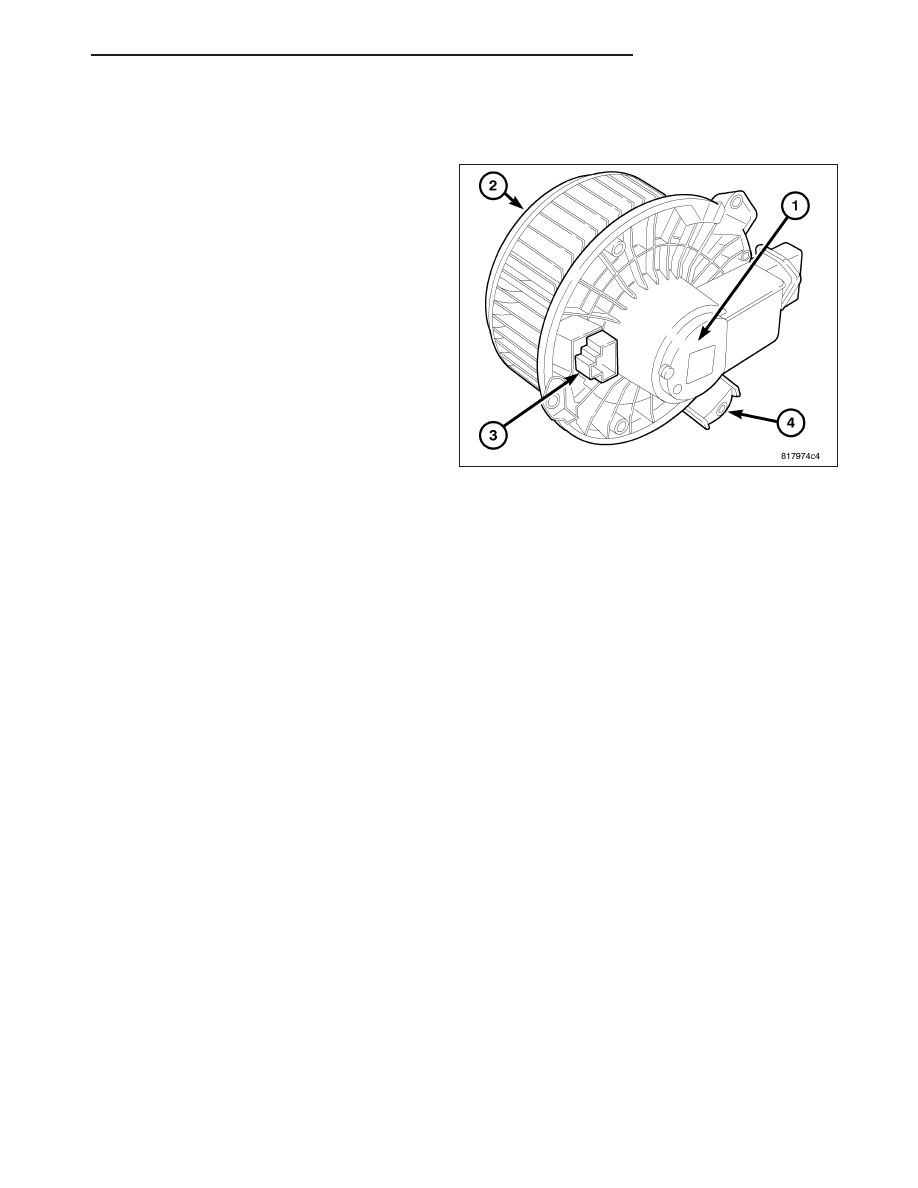
MOTOR-BLOWER
DESCRIPTION
The blower motor (1) is used to control the velocity of
air moving through the HVAC housing by spinning the
blower wheel (2) within the HVAC air inlet housing at
the selected speed.
The blower motor is a 12-volt, direct current (DC)
motor mounted within a plastic housing with an inte-
gral wire harness connector (3) and three mounting
tabs (4). The squirrel cage-type blower wheel is
secured to the blower motor shaft and is positioned
within the air inlet housing on the passenger side of
the HVAC housing.
OPERATION
The blower motor is used to control the velocity of air moving through the HVAC housing by spinning the blower
wheel within the HVAC air inlet housing at the selected speed.
The blower motor will operate whenever the ignition switch is in the Run position and the blower motor control is in
any position except Off. The blower motor receives battery current through the totally integrated power module
(TIPM) whenever the ignition switch is in the Run position.
Blower motor speed is controlled by regulating the ground path through or around the blower motor resistor and
through the blower motor control located within the A/C-heater control.
The blower motor can be accessed for service from underneath the instrument panel.
NOTE: The blower motor is supplied with a 12V feed from the TIPM, through the blower motor resistor,
whenever the ignition switch is in the RUN position. Due to an open circuit condition within the blower
motor control switch the TIPM is UNABLE to detect an OPEN circuit for the blower motor.
The blower motor control system is diagnosed using a scan tool (refer to 24 - HVAC Electrical Diagnostics for more
information).
The blower motor and blower wheel are factory balanced and cannot be adjusted or repaired. If faulty or damaged,
the blower motor and wheel must be replaced as an assembly.
DIAGNOSIS AND TESTING
BLOWER MOTOR
WARNING: Disable the airbag system before attempting any steering wheel, steering column, or instrument
panel component diagnosis or service. Disconnect and isolate the negative battery (ground) cable, then wait
two minutes for the airbag system capacitor to discharge before performing further diagnosis or service.
Failure to take the proper precautions could result in accidental airbag deployment and possible personal
injury or death.
PM
DISTRIBUTION
24 - 109