Dodge Caliber. Manual - part 1417


  Index      Dodge     Dodge Caliber - service repair manual 2007 year


Search            


Content   ..  1415  1416  1417  1418   ..


Dodge Caliber. Manual - part 1417


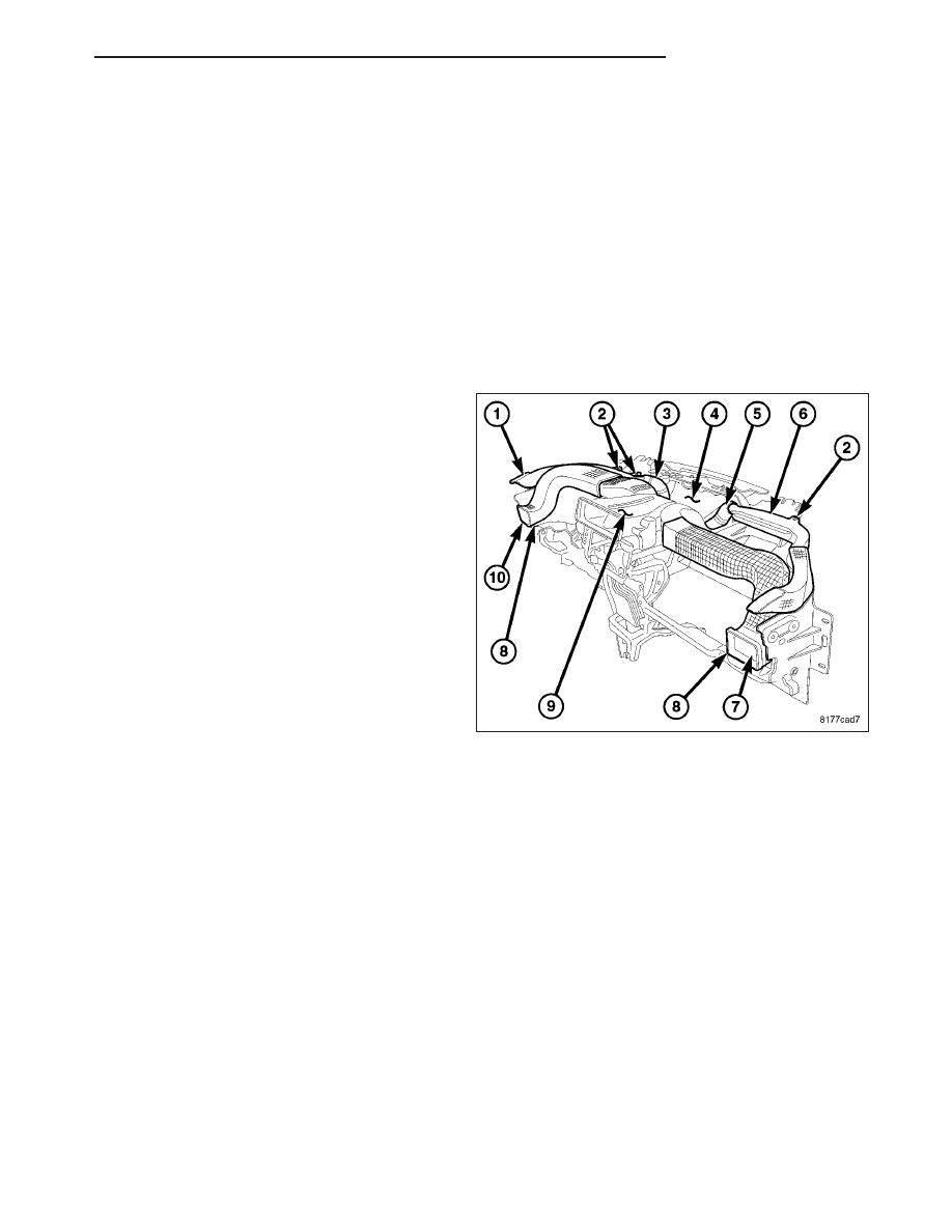
DUCT-INSTRUMENT PANEL DEMISTER

REMOVAL

WARNING: Disable the airbag system before attempting any steering wheel, steering column, or instrument
panel component diagnosis or service. Disconnect and isolate the negative battery (ground) cable, then wait
two minutes for the airbag system capacitor to discharge before performing further diagnosis or service.
This is the only sure way to disable the airbag system. Failure to take the proper precautions could result
in accidental airbag deployment and possible personal injury or death.

NOTE: The left and right side demister ducts are serviced only as an assembly with the left or right side
instrument panel duct.

NOTE: Illustration shown with instrument panel removed from vehicle for clarity.

NOTE: LHD model shown. RHD model similar.

1. Remove the instrument panel top cover (refer to 23

-

BODY/INSTRUMENT

PANEL/INSTRUMENT

PANEL TOP COVER - REMOVAL).

2. Disconnect the left side demister hose (3) and right

side demister hose (5) from the defroster duct (4).

3. Remove the screws (2) that secure each demister

duct (1 and 6) to the instrument panel support.

4. Remove the push-pin fastener (8) that secures

each instrument panel duct (7 and 10) to the instru-
ment panel support.

5. Disconnect the left and right side instrument panel

ducts from the center duct (9).

6. Remove the each demister duct and instrument

panel duct as an assembly from the instrument
panel.

INSTALLATION

NOTE: The left and right side demister ducts are serviced only as an assembly with the left or right side
instrument panel duct.

NOTE: Illustration shown with instrument panel removed from vehicle for clarity.

PM

DISTRIBUTION

24 - 85

NOTE: LHD model shown. RHD model similar.

1. Position the left and right side demister ducts (1

and 6) and the left and right side instrument panel
ducts (7 and 10) onto the top of the instrument
panel as assemblies.

2. Connect the left and right side instrument panel

ducts to the center duct (9). Make sure the ducts
are fully engaged to each other.

3. Install the push-pin fastener (8) that secures each

instrument panel duct to the instrument panel sup-
port.

4. Install the screws (2) that secure each demister

duct to the instrument panel support. Tighten the
screws to 2.2 N·m (20 in. lbs.).

5. Connect the left and right side demister hoses (3

and 5) to the defroster duct (4). Make sure the
hoses are fully engaged to the defroster and
demister ducts.

6. Install the instrument panel top cover (refer to 23 - BODY/INSTRUMENT PANEL/INSTRUMENT PANEL TOP

COVER - INSTALLATION).

24 - 86

DISTRIBUTION

PM

FILTER-PARTICULATE AIR

DESCRIPTION

Some models are equipped with a particulate air filter
(1) that helps purify the outside air entering the HVAC
housing. The filter is mounted in the passenger com-
partment, behind the glove box bin.

The filter should be replaced at least once a year or
every 24,000 km (15,000 miles) and checked if heat-
ing-A/C

system

performance

seems

lower

than

expected. The particulate air filter is labeled with an
arrow (2) to indicate the direction of air flow through
the filter.

REMOVAL

NOTE: LHD model shown in illustrations. RHD model similar.

NOTE: Illustration shown with instrument panel
removed for clarity.

1. Remove the glove box bin (refer to 23 - BODY/IN-

STRUMENT

PANEL/BIN-GLOVE

BOX

-

REMOVAL).

2. Disengage the four retaining tabs (1) that secure

the particulate air filter cover (2) to the passenger
side of the HVAC housing (3) and remove the
cover.

PM

DISTRIBUTION

24 - 87

3. Remove the particulate air filter (1) from the HVAC

housing (2) by pulling the filter element straight out
of the housing.

INSTALLATION

NOTE: The particulate air filter is labeled with an arrow to indicate air flow direction through the filter. Make
sure to properly install the particulate air filter. Failure to properly install the filter will result in the need to
replace the filter sooner than required by design.

NOTE: LHD model shown in illustrations. RHD model similar.

1. Install the particulate air filter (1) into the filter

opening in the HVAC housing (2). Insert the partic-
ulate air filter directly into the housing with the
arrow on the filter pointing to the floor.

24 - 88

DISTRIBUTION

PM


Content   ..  1415  1416  1417  1418   ..