Content .. 1414 1415 1416 1417 ..
Dodge Caliber. Manual - part 1416
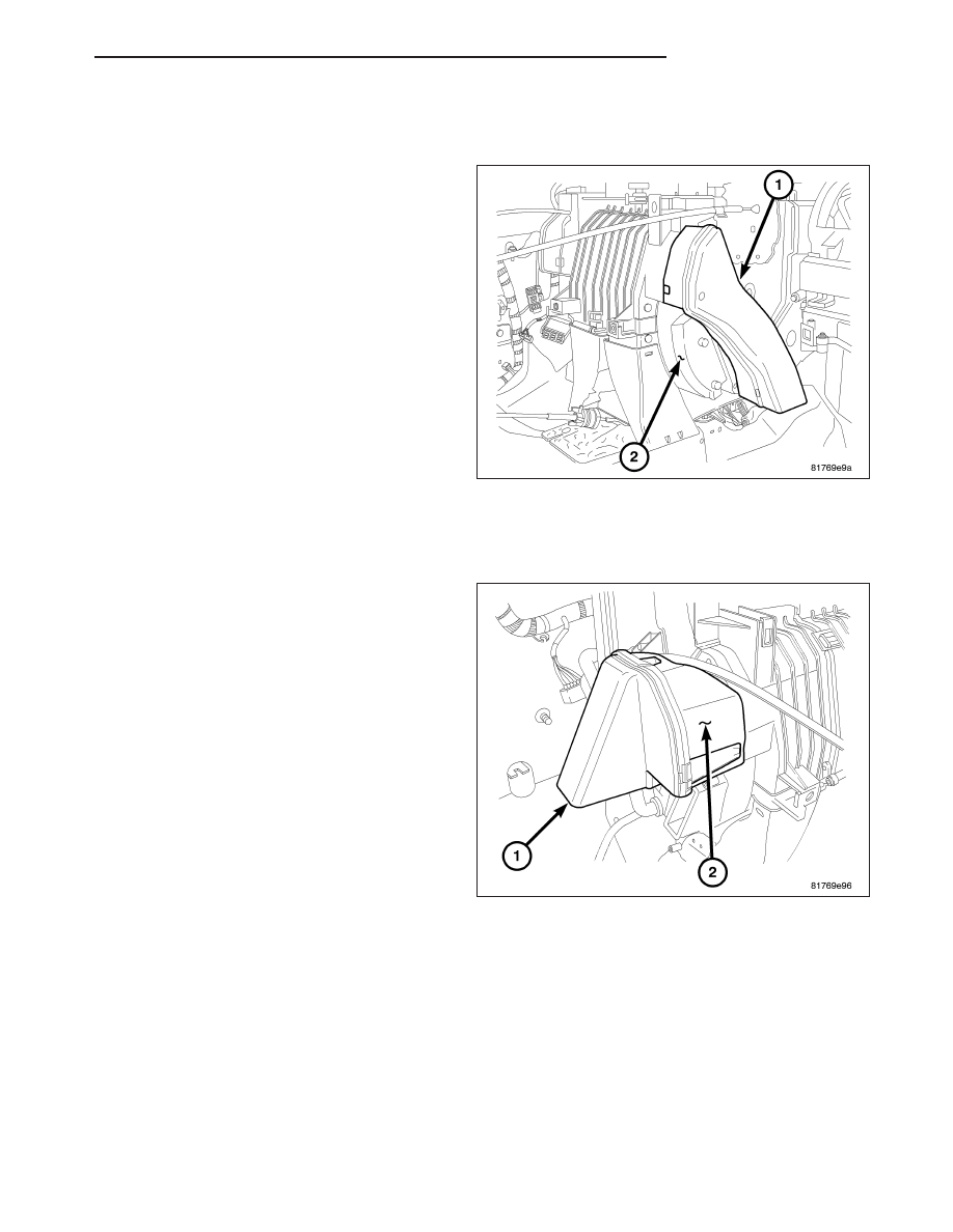
INSTALLATION
RIGHT FRONT FLOOR DUCT
NOTE: LHD model shown. RHD model similar.
1. Connect the right front floor duct (1) to the right
side of the HVAC housing (2). Make sure the duct
is fully engaged to the housing.
2. Install the instrument panel (refer to 23 - BODY/IN-
STRUMENT
PANEL/ASSEMBLY-INSTRUMENT
PANEL - INSTALLATION).
LEFT FRONT FLOOR DUCT
NOTE: Illustration shown with instrument panel removed for clarity.
NOTE: LHD model shown. RHD model similar.
1. Connect the left front floor duct (1) to the left side
of the HVAC housing (2). Make sure the duct is
fully engaged to the housing.
2. Install the screw that secures the left front floor
duct to the left side of the HVAC housing. Tighten
the screw to 2 N·m (17 in. lbs.).
3. On LHD models, install the steering column open-
ing cover (refer to 23 - BODY/INSTRUMENT PAN-
EL/COVER-STEERING
COLUMN
OPENING
-
INSTALLATION).
4. On RHD models, install the instrument panel cover
(Refer to 23 - BODY/INSTRUMENT PANEL/COV-
ER-INSTRUMENT PANEL - INSTALLATION).
PM
DISTRIBUTION
24 - 81