Dodge Caliber. Manual - part 1400


  Index      Dodge     Dodge Caliber - service repair manual 2007 year


Search            


Content   ..  1398  1399  1400  1401   ..


Dodge Caliber. Manual - part 1400


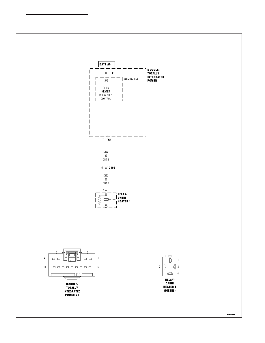
B10B4–CABIN HEATER 1 CONTROL CIRCUIT LOW (TIPM)

For a complete wiring diagram Refer to Section 8W

PM

HEATING & AIR CONDITIONING ELECTRICAL DIAGNOSTICS

24 - 17

When Monitored:
With the ignition on, the Cabin Heater Relay 1 commanded on.

Set Condition:
If the Totally Integrated Power Module detects the (K132) Cabin Heater Relay 1 Control circuit is shorted to
ground.

Possible Causes

(K132) CABIN HEATER RELAY 1 CONTROL CIRCUIT SHORTED TO GROUND

CABIN HEATER 1 RELAY

TOTALLY INTEGRATED POWER MODULE (TIPM)

Diagnostic Test

1.

VERIFY THAT THE DTC IS ACTIVE

Turn the ignition on.

With the scan tool, erase DTCs.

With the scan tool, actuate the Cabin Heater 1 Relay.

Monitor the scan tool for at least two minutes.

With the scan tool, read DTCs.

Does the scan tool display active: B10B4–CABIN HEATER 1 CONTROL CIRCUIT LOW?

Yes

>> Go To 2

No

>> The condition that caused this symptom is currently not present. Check for an intermittent condition by

inspecting the related wiring harness for chafed, pierced, pinched, and partially broken wires. Also,
inspect the related connectors for broken, bent, pushed out, spread, corroded, or contaminated termi-
nals. Repair as necessary.

Perform the BODY VERIFICATION TEST VER 1. (Refer to 8 - ELECTRICAL/ELECTRONIC CONTROL
MODULES/FRONT CONTROL MODULE - DIAGNOSIS AND TESTING).

2.

CHECK (K132) CABIN HEATER RELAY 1 OUTPUT CIRCUIT FOR SHORT TO GROUND

Turn the ignition off.

Disconnect the TIPM C1 harness connector.

Remove the Cabin Heater Relay 1.

Using an ohm meter measure the resistance between the (K132) Cabin
Heater Relay 1 Output circuit and ground.

Does the ohm meter read open circuit?

Yes

>> Go To 3

No

>> Repair the (K132) Cabin Heater Relay 1 Output circuit for a

short to ground.

Perform the BODY VERIFICATION TEST VER 1. (Refer to
8 - ELECTRICAL/ELECTRONIC CONTROL MODULES/
FRONT

CONTROL

MODULE

-

DIAGNOSIS

AND

TESTING).

24 - 18

HEATING & AIR CONDITIONING ELECTRICAL DIAGNOSTICS

PM

3.

TOTALLY INTEGRATED POWER MODULE (TIPM)

Turn the ignition on.

With the scan tool, erase DTCs.

With the scan tool, actuate the Cabin Heater 1 Relay.

Monitor the scan tool for at least two minutes.

With the scan tool, read DTCs.

Does the scan tool display active: B10B4–CABIN HEATER 1
CONTROL CIRCUIT LOW?

Yes

>> Replace the Totally Integrated Power Module (TIPM) in

accordance with the service information.

Perform the BODY VERIFICATION TEST VER 1. (Refer to
8 - ELECTRICAL/ELECTRONIC CONTROL MODULES/
FRONT CONTROL MODULE - DIAGNOSIS AND TEST-
ING).

No

>> Replace the Cabin Heater Relay 1 in accordance with the

service information.

Perform the BODY VERIFICATION TEST VER 1. (Refer to 8 - ELECTRICAL/ELECTRONIC CONTROL
MODULES/FRONT CONTROL MODULE - DIAGNOSIS AND TESTING).

PM

HEATING & AIR CONDITIONING ELECTRICAL DIAGNOSTICS

24 - 19

B10B5–CABIN HEATER 1 CONTROL CIRCUIT HIGH (TIPM)

For a complete wiring diagram Refer to Section 8W

24 - 20

HEATING & AIR CONDITIONING ELECTRICAL DIAGNOSTICS

PM


Content   ..  1398  1399  1400  1401   ..