Content .. 1320 1321 1322 1323 ..
Dodge Caliber. Manual - part 1322
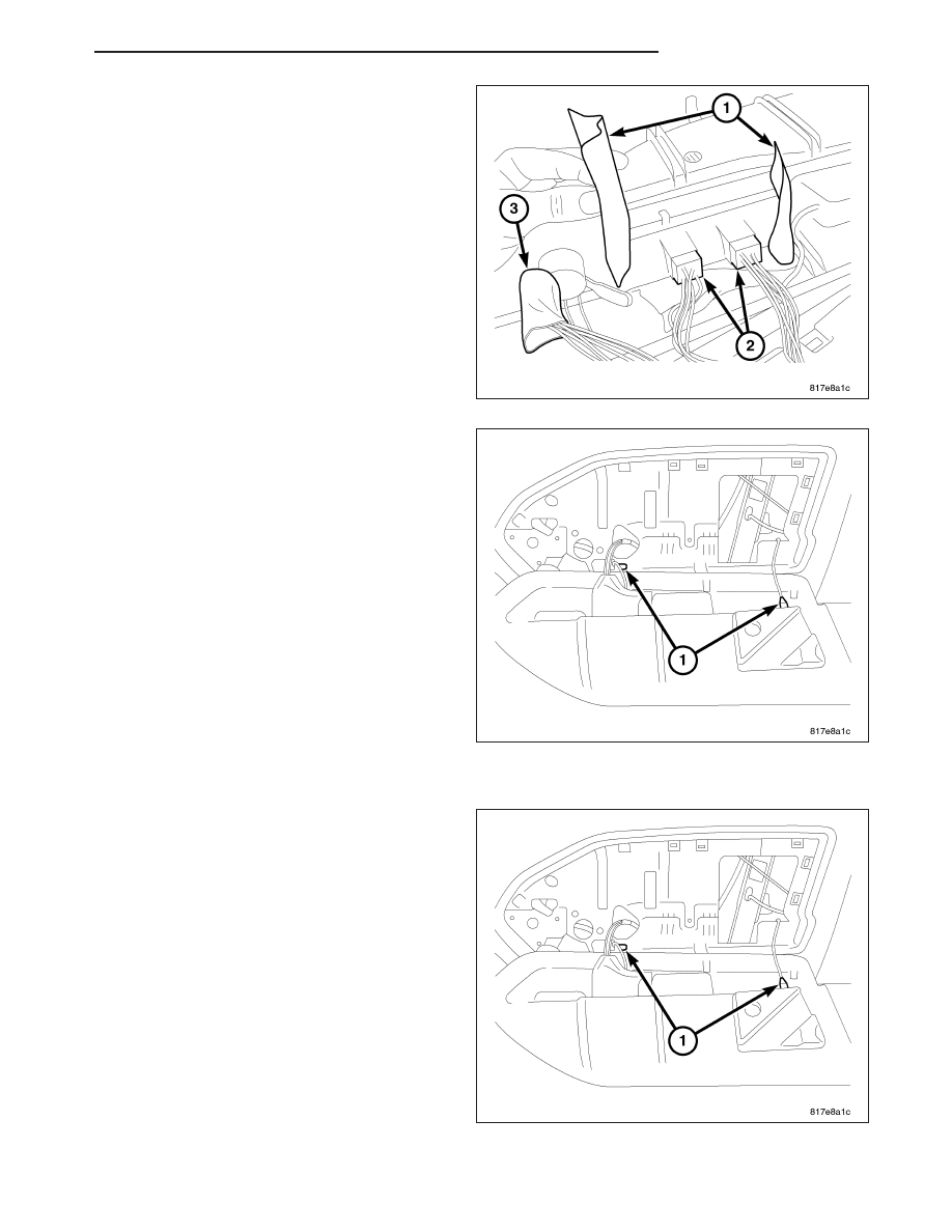
4. Remove sock seal (1) and (3) that wraps around
switch bezel and wire harness. Disconnect wire
connectors (2).
5. Remove switch bezel from bolster.
6. Remove bolster by unsnapping plastic tethers (1)
from bolster back side of surface.
INSTALLATION
1. Connect bolster to door module tethers (1).
PM
DOOR - FRONT
23 - 25