Dodge Caliber. Manual - part 1312


  Index      Dodge     Dodge Caliber - service repair manual 2007 year


Search            


Content   ..  1310  1311  1312  1313   ..


Dodge Caliber. Manual - part 1312


a.

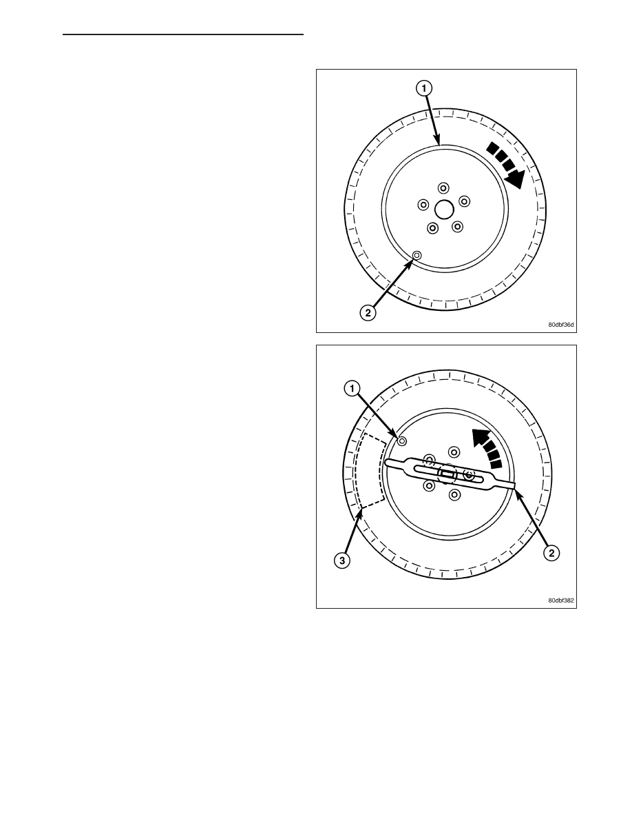
Rotating Wheel Tire Changers - Once the
wheel is mounted to the changer, position the
sensor valve stem (2) approximately 210° from
the head of the changer (located at 1) in a
clockwise direction before rotating the wheel
(also in a clockwise direction) to mount the tire.
Use this procedure on both the upper and
lower tire beads.

b. Rotating Tool Tire Changers - Position the

wheel on the changer so that the sensor valve
stem (1) is located approximately 210° clock-
wise from the installation end of the mounting/
dismounting tool (2) once the tool is mounted
for tire installation. Make sure the sensor is
clear of the lower bead breaker area (3) to
avoid damaging the sensor when the breaker
rises. Rotate the tool (2) in a counterclockwise
direction to mount the tire. Use this procedure
on both the upper and lower tire beads.

PM

TIRES/WHEELS - SERVICE INFORMATION

22 - 75

6. Adjust air pressure to that listed on Tire Inflation

Pressure Label (Placard) provided with vehicle
(applied to driver’s side B-pillar). Make sure origi-
nal style and color 
valve stem cap is securely
installed to keep moisture out of sensor.

7. Install tire and wheel assembly (1) on vehicle

(Refer to 22 - TIRES/WHEELS - INSTALLATION).
Tighten wheel mounting nuts (3) to 135 N·m (100
ft. lbs.).

8. Lower vehicle.

NOTE: Once a sensor has been replaced and the
vehicle has remained stationary (0 mph (0 km/h))
for more than 19 minutes, the WCM automatically
learns and stores the sensor’s ID while driving.

9. Drive vehicle for a minimum of 10 minutes while

maintaining a continuous speed above 15 mph (24
km/h). During this time the system will learn the
new sensor ID code and will clear any DTC’s automatically (refer to above note).

NOTE: If a sensor cannot be trained, refer to appropriate diagnostic information.

22 - 76

TIRES/WHEELS - SERVICE INFORMATION

PM

TRANSPONDER - TPM

DESCRIPTION

Vehicles equipped with the premium TPM system use transponders, sometimes referred to as trigger modules, to
provide the Wireless Control Module (WCM), commonly referred to as the Sentry Key Remote Entry Module
(SKREEM), with the location of the tire pressure sensors on the vehicle. A transponder is located in three of the four
wheel wells on the vehicle The transponders are located in the left front, left rear and right rear wheel wells behind
the wheelhouse splash shields. Only three transponders are necessary to locate the four rotating sensors because
the WCM can determine the location of the fourth by using the process-of-elimination theory. Once the system
knows the location of the first three sensors, it assumes the location of the fourth tire pressure sensor is in the right
front tire.

OPERATION

On vehicles equipped with the premium TPM system, the Wireless Control Module (WCM), commonly referred to as
the Sentry Key Remote Entry Module (SKREEM), uses transponders (trigger modules) located in three of the four
wheel wells on the vehicle to provide it with the location of the tire pressure sensors on the vehicle. Like the base
system, the WCM receives RF signals from all four rotating wheel speed sensors. When the WCM needs to know
which sensor is located at a particular location on the vehicle, it directs the transponder at that location to send out
a low frequency signal to excite the nearby sensor. The WCM then receives that excited signal and knows where
that sensor is located. This auto-locating process only happens in the first 10 minutes of any WCM cycle while
traveling at speeds above 20 mph (32 km/h) (Each WCM cycle ends when the vehicle has been shut off for a time
period of approximately 15 minutes or longer). Once the WCM has performed this to the three locations that have
transponders (left front, left rear and right rear wheel wells), it uses the process-of-elimination theory to know that
the fourth sensor ID signal is coming from the right front tire sensor.

REMOVAL

FRONT

1. Remove the wheelhouse splash shield at the transponder requiring service. (Refer to 23 - BODY/EXTERIOR/F

WHEELHOUSE SPLASH SHIELD - REMOVAL)

2. Disconnect the wiring harness connector (2) at the

transponder (1).

3. Remove the mounting nuts (3), then remove the

transponder (1).

REAR

1. Remove the wheelhouse splash shield at the transponder requiring service. (Refer to 23 - BODY/EXTERIOR/

REAR WHEELHOUSE SPLASH SHIELD - REMOVAL)

PM

TIRES/WHEELS - SERVICE INFORMATION

22 - 77

2. Disconnect the wiring harness connector (3) at the

transponder (1).

3. Remove the mounting nuts (2), then remove the

transponder (1).

INSTALLATION

FRONT

1. Position the transponder (1) and install the mount-

ing nuts (3).

2. Connect the wiring harness connector (2) to the

transponder (1).

3. Install the wheelhouse splash shield and all compo-

nents removed to access it. (Refer to 23 - BODY/
EXTERIOR/F WHEELHOUSE SPLASH SHIELD -
INSTALLATION)

4. Perform the TPM Diagnostic Verification Test.

(Refer to 22 - TIRES/WHEELS/TIRE PRESSURE
MONITORING - DIAGNOSIS AND TESTING)

22 - 78

TIRES/WHEELS - SERVICE INFORMATION

PM


Content   ..  1310  1311  1312  1313   ..