Dodge Caliber. Manual - part 1262


  Index      Dodge     Dodge Caliber - service repair manual 2007 year


Search            


Content   ..  1260  1261  1262  1263   ..


Dodge Caliber. Manual - part 1262


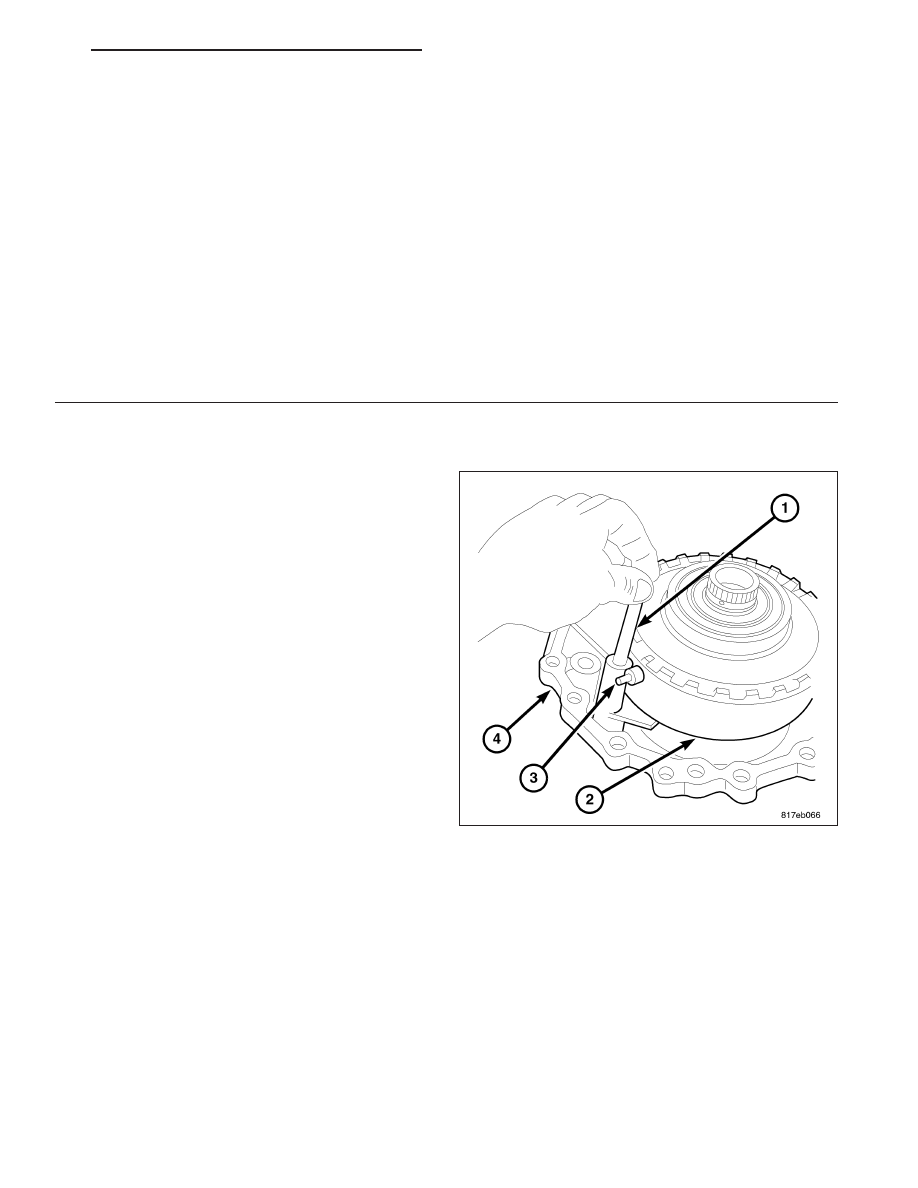
1. Refer to the exploded views as necessary when performing the following steps.

2. Install the primary sheave (2) with the sheave

height sensor, (3) spring and pin (1) into the belt
side case.

1 - O-RING

24 - BAFFLE PLATE

2 - SIDE OIL SEAL

25 - DRIVEN SPROCKET (OIL PUMP)

3 - ADJUSTABLE SHIM

26 - BAFFLE PLATE

4 - OUTER RACE

27 - OIL PUMP

5 - REDUCTION GEAR ASSEMBLY

28 - LIP SEAL

6 - OUTER RACE

29 - SNAP RING

7 - ADJUSTABLE SHIM

30 - DRIVEN PLATES

8 - OUTER RACE

31 - NEEDLE BEARING

9 - DIFFERENTIAL ASSEMBLY

32 - SUN GEAR

10 - OUTER RACE

33 - NEEDLE BEARING

11 - FORWARD CLUTCH ASSEMBLY

34 - PLANETARY CARRIER

12 - NEEDLE BEARING

35 - NEEDLE BEARING

13 - SEAL RING

36 - SNAP RING

14 - OIL PUMP COVER

37 - RETAINING PLATE

15 - BAFFLE PLATE

38 - DRIVEN PLATES

16 - BRACKET

39 - DISH PLATE

17 - ADJUSTABLE SHIM

40 - SNAP RING

18 - ADJUSTABLE SHIM

41 - RETAINING PLATE

19 - CONVERTER HOUSING

42 - SPRING RETAINER ASSEMBLY

20 - CONVERTER HOUSING OIL SEAL

43 - REVERSE PLATE PISTON

21 - OIL PUMP CHAIN

44 - DETENT SPRING

22 - DRIVE SPROCKET

45 - TRANSAXLE CASE

23 - THRUST WASHER

PM

AUTOMATIC - CVT-SERVICE INFORMATION

21 - 347

3. Install the secondary sheave positioning shim (3)

into the belt side cover.

4. Install Sheave Compressor 9874 (1) and Press

Insert 8513 A, (2) onto secondary sheave.

21 - 348

AUTOMATIC - CVT-SERVICE INFORMATION

PM

5. Move the secondary sheave (3) close enough to

the primary (2) sheave to allow the drive belt (1) to
be

put

around

both

secondary

and

primary

sheaves.

NOTE: The drive belt is directional and will need
to be installed in the same direction as noted in
disassembly, if installed incorrectly failure will
accrue

6. Install the drive belt (1).

CAUTION: Do not over tighten the compressor
tool. Tighten to no more than 7 N·m (50 in. lbs.)

7. Compress the secondary (3) sheave to the stop.

8. Install the drive belt (1) around both secondary (3)

and primary (2) sheaves.

9. Install the primary sheave into place.

10. Remove Sheave Compressor 9874 and Press

Insert 8513A from the primary sheave.

11. Install the bolts (2) that hold both sheaves to the

case (1).

PM

AUTOMATIC - CVT-SERVICE INFORMATION

21 - 349

CAUTION: Remove moisture, oil, and used sealant
from the sealant application surface. Make sure
that the starting point and the ending point are
between two bolt holes.

12. Apply Loctite 509 sealer onto the belt side of the

transaxle case.

13. Install the belt side assembly to the transaxle

case.

14. Install the case bolts (1) to hold the drive belt

assembly (2) to the transaxle. Torque to 45 N·m
(33 ft.lbs.).

CAUTION: Inspect the reverse brake piston and, if
damaged, replace it before installation. Apply CVT
fluid to the seal when installing the reverse brake
piston.

NOTE: Rotate reverse brake piston into place

15. Rotate and install the reverse brake piston (1) into

the transaxle case.

21 - 350

AUTOMATIC - CVT-SERVICE INFORMATION

PM


Content   ..  1260  1261  1262  1263   ..