Content .. 1161 1162 1163 1164 ..
Dodge Caliber. Manual - part 1163
STEERING COLUMN CONTROL MODULE
DESCRIPTION
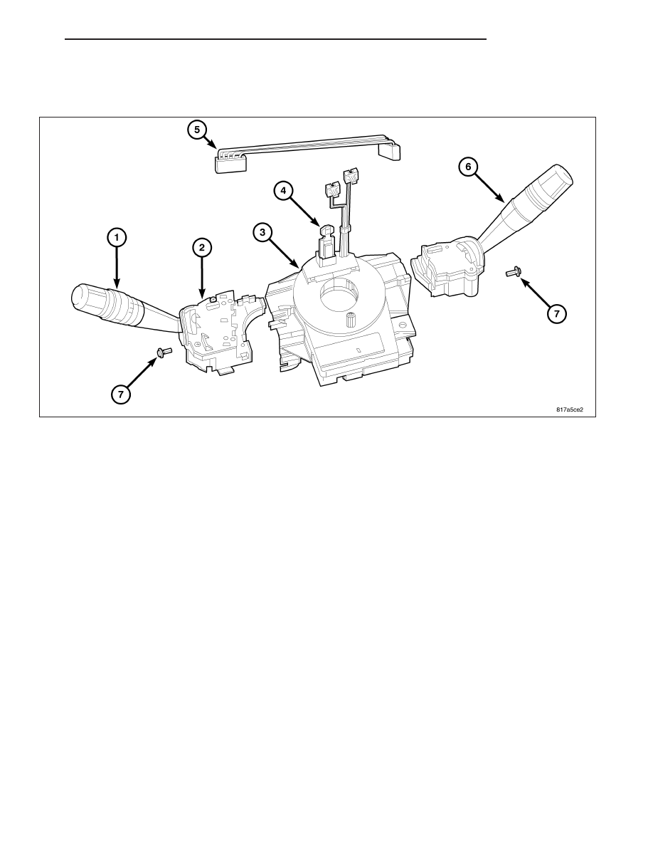
This vehicle is equipped with a Steering Column Control Module (SCCM) The SCCM is secured near the top of the
steering column below the steering wheel and is completely concealed beneath the steering column shrouds. It is
installed as a modular unit that supports the left (lighting) multi-function switch (1) and right (wiper) multi-function
switch (6). The controls for each of these switches extend through appropriate clearance holes provided in the
steering column shrouds.
The microprocessor-based Steering Control Module (SCM) (2) utilizes integrated circuitry and information carried on
the Controller Area Network (CAN) data bus along with several hard wired analog and multiplexed inputs to monitor
both the right and left multi-function switches. The SCCM uses a Local Interconnect Network (LIN) data bus for
exterior lighting and wiper functions. The LIN data is sent to the Cab Compartment Node (CCN) and the CCN then
sends it out on the CAN data bus (Refer to 8 - ELECTRICAL/ELECTRONIC CONTROL MODULES/COMMUNICA-
TION - DESCRIPTION - CAN BUS). The SCCM is available for service replacement as a unit or each individual
component:
•
Clockspring (with integral Steering Angle Sensor if equipped)
•
Left Multi-Function Switch
•
Right Multi-Function Switch
OPERATION
The Steering Control Module (SCM) communicates over the Local Interconnect Network (LIN) data bus with other
electronic modules in the vehicle and/or a diagnostic scan tool. The horn switch circuits pass through the clock-
spring to the Cab Compartment Node (CCN) and the CCN sends a CAN message to the Totally Integrated Power
Module (TIPM) to control the horn. The CCN stores Diagnostic Trouble Codes (DTC’s) for the SCM. The right
(wiper) multi-function switch has several inputs to the CCN.
The SCM is connected to a fused B(+) circuit and receives a path to ground at all times. These connections allow
it to remain functional regardless of the ignition switch position. The driver airbag squib circuits of the clockspring,
the horn, and the speed control switch circuits pass through the SCM, but the SCM does not monitor, and has no
control outputs related to these circuits. Any other input to the SCM that would cause a vehicle system to function
but does not require that the ignition switch be in the On position, such as turning on the lights or sounding the
horn, prompts the SCM to wake up and transmit on the CAN data bus.
PM
COLUMN
19 - 39