Dodge Caliber. Manual - part 1068


  Index      Dodge     Dodge Caliber - service repair manual 2007 year


Search            


Content   ..  1066  1067  1068  1069   ..


Dodge Caliber. Manual - part 1068


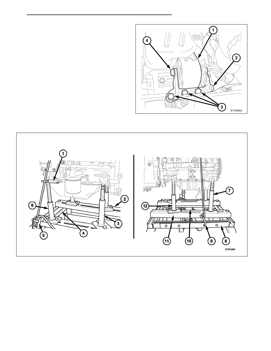
75. Remove right engine mount through bolt (4).

76. Raise vehicle away from engine and transaxle.

77. Separate engine from transaxle.

INSTALLATION - ENGINE ASSEMBLY

1. Position engine and transmission assembly under vehicle and slowly lower the vehicle over the engine/transaxle

assembly.

2. Continue lowering vehicle until engine/transaxle aligns to mounting locations. Install mounting bolts at the right

and left engine/transaxle mount bolts and Tighten bolts to 118 N·m (87 ft. lbs.).

3. Remove safety straps from engine/transaxle assembly. Slowly raise vehicle enough to remove the engine dolly

and cradle.

PM

ENGINE 2.0L WORLD

9 - 1559

4. Remove Adapter 9704 (1).

5. Install pcm bracket.

6. Install maniverter assembly and upper lower heat

shields.

7. Install oxygen sensor and connect electrical con-

nector.

8. Install coolant manifold assembly.

9. Install transaxle linkage and adjust as necessary.

10. Install transaxle vent hose.

11. Connect transaxle electrical connectors.

12. Install Ground strap near right strut tower.

13. Raise vehicle.

14. Pull engine forward and restrain engine.

NOTE: Be sure to install O-ring prior to installing
PTU assembly.

15. Install PTU.

16. Remove engine restraint.

17. Install front mount bracket and tighten bolts.

18. Install frame cross member.

19. Install front engine mount.

20. Install rear mount bracket.

21. Install rear mount and tighten bolts.

22. Connect CKP electrical connector.

23. Install maniverter to exhaust pipe bolts (1) and

tighten bolts.

24. Align driveshaft marks and install and heat shield.

25. Install generator

26. Install A/C bracket.

27. Install A/C lines on compressor and install com-

pressor.

28. Install lower bell housing bolts and tighten bolts.

29. Align torque converter and flex plate mark. Install

torque converter bolts and tighten.

9 - 1560

ENGINE 2.0L WORLD

PM

30. Install inspection cover (1).

31. Install transaxle electrical connectors.

32. Connect trans cooler lines.

33. Install coolant hoses at transmission cooler.

34. Install axles.

35. Install ball joint pinch bolts and tighten.

36. Install axle nuts and tighten.

37. Install splash shields.

38. Install wheels.

39. Install new oil filter.

40. Lower vehicle.

41. Install transaxle filler tube.

42. Install upper idler pulley.

43. Install power steering pump.

44. Install power steering line support bracket.

45. Install power steering pump.

46. Install accessory drive belt.

47. Connect electrical connectors at block ground, starter, A/C compressor, knock sensor, Oil pressure sensor, gen-

erator, Coolant temperature sensor at block, and block heater.

48. Install intake manifold and tighten bolts.

49. Install throttle body support bracket (1).

50. Install engine oil dip stick.

51. Install PCV hose to valve cover.

52. Connect manifold flow control valve and electronic

throttle control electrical connectors and fasten
harness to intake.

53. Install vacuum lines at throttle body and intake

manifold.

54. Install intake air tube on throttle body.

55. Connect engine harness electrical connectors.

56. Install upper radiator support bracket.

57. Install coolant hoses at coolant manifold.

58. Install grill trim panel.

59. Install coolant reservoir and connect hose.

60. Connect fuel line to fuel rail.

61. Install battery tray and battery.

62. Connect battery cables.

63. Install air cleaner housing and connect inlet air hose.

64. Install fresh air inlet.

65. Fill with coolant.

66. Fill with oil.

CAUTION: Do NOT run the engine with a vacuum pump in operation or with a vacuum present within the
A/C system. Failure to follow this caution will result in serious A/C compressor damage.

67. Evacuate the refrigerant system (refer to 24 - HEATING & AIR CONDITIONING/PLUMBING - STANDARD

PROCEDURE - REFRIGERANT SYSTEM EVACUATE).

68. Charge the refrigerant system (refer to 24 - HEATING & AIR CONDITIONING/PLUMBING - STANDARD PRO-

CEDURE - REFRIGERANT SYSTEM CHARGE).

69. Start engine and check for leaks.

PM

ENGINE 2.0L WORLD

9 - 1561

SPECIFICATIONS

2.4L ENGINE

GENERAL SPECIFICATIONS

DESCRIPTION

SPECIFICATION

Metric

Standard

Type

In-Line OHV, DOHC

Number of Cylinders

4

Firing Order

1-3-4-2

Compression Ratio

9.5:1

Max. Variation Between Cylinders

25%

Displacement

2.4 Liters

148 cu. in.

Bore

88 mm

3.465 in.

Stroke

97 mm

3.819 in.

Compression Pressure

1172-1551 kPa

170-225 psi

CYLINDER BLOCK

DESCRIPTION

SPECIFICATION

Metric

Standard

Material

Cast Aluminum

Cylinder Bore Diameter

87.4924-87.5076 mm

3.4446-3.4452 in.

A

88.0-88.010

3.4645-3.4649 in.

B

88.010-88.020

3.4649-3.4653 in.

C

88.020-88.030

3.4653-3.4657 in.

Out-of-Round (Max.)

0.051 mm

0.002 in.

Taper (Max.)

0.051 mm

0.002 in.

PISTONS

DESCRIPTION

SPECIFICATION

Metric

Standard

Piston Diameter

87.456-87.474 mm

3.4431-3.4439 in.

Clearance @ 24.6 mm (0.551 in.)
from bottom of skirt (Non-Turbo)

0.018-0.0516 mm

0.0007-0.0020 in.

Clearance @ 22 mm (0.866 in.)
from bottom of skirt (Turbo)

0.046-0.064 mm

0.0018-0.0025 in.

Weight

345-355 grams

12.17-12.52 oz.

Land Clearance (Diametrical)

0.563-0.621 mm

0.022-0.024 in.

Piston Length

66.25 mm

2.608 in.

Piston Ring Groove Depth No. 1

3.946-4.045 mm

0.155-0.159 in.

Piston Ring Groove Depth No. 2

4.555-4.680 mm

0.179-0.184 in.

9 - 1562

ENGINE 2.0L WORLD

PM


Content   ..  1066  1067  1068  1069   ..