Dodge Caliber. Manual - part 1067


  Index      Dodge     Dodge Caliber - service repair manual 2007 year


Search            


Content   ..  1065  1066  1067  1068   ..


Dodge Caliber. Manual - part 1067


MEASURING BEARING CLEARANCE USING PLASTIGAGE

Engine crankshaft bearing clearances can be deter-
mined by use of Plastigage or equivalent. The follow-
ing is the recommended procedure for the use of
Plastigage:

1.

Remove oil film from surface to be checked. Plas-

tigage is soluble in oil.

2. Place a piece of Plastigage across the entire width

of the bearing shell in the cap approximately 6.35
mm (1/4 in.) off center and away from the oil holes.
(In addition, suspected areas can be checked by
placing the Plastigage in the suspected area).
Torque the bearing cap/bed plate bolts of the bear-
ing being checked to the proper specifications.

3. Remove the bearing cap and compare the width of

the flattened Plastigage with the metric scale pro-
vided on the package. Locate the band closest to
the same width. This band shows the amount of
clearance in thousandths of a millimeter. Differ-
ences in readings between the ends indicate the
amount of taper present. Record all readings taken. Compare clearance measurements to specs found in engine
specifications (Refer to 9 - ENGINE - SPECIFICATIONS). Plastigage generally is accompanied by two
scales. One scale is in inches, the other is a metric scale.

NOTE: Plastigage is available in a variety of clearance ranges. Use the most appropriate range for the spec-
ifications you are checking.

4. Install the proper crankshaft bearings to achieve the specified bearing clearances.

REMOVAL - ENGINE ASSEMBLY

1. Perform fuel pressure release procedure, then dis-

connect and remove fuel line (Refer to 14 - FUEL
SYSTEM/FUEL DELIVERY - STANDARD PROCE-
DURE).

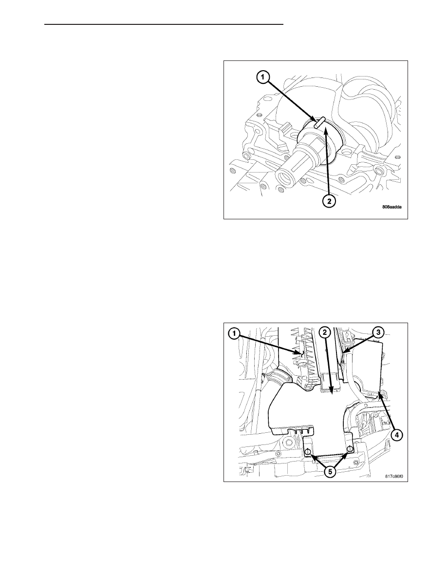
2. Remove air cleaner housing assembly (1) and

clean air hose (Refer to 9 - ENGINE/AIR INTAKE
SYSTEM/AIR CLEANER HOUSING - REMOVAL).

3. Disconnect both cables from battery.

4. Remove battery and battery tray.

5. Discharge air conditioning system, if equipped

(Refer to 24 - HEATING & AIR CONDITIONING -
STANDARD PROCEDURE).

6. Drain cooling system (Refer to 7 - COOLING/EN-

GINE - STANDARD PROCEDURE).

PM

ENGINE 2.0L WORLD

9 - 1555

7. Remove coolant reservoir (3).

8. Remove grill trim panel.

9. Remove upper radiator hose from radiator and

coolant manifold.

10. Remove upper radiator hose support.

11. Remove lower radiator hose at coolant manifold.

12. Remove coolant hose from coolant manifold.

13. Disconnect the following electrical connectors,

variable valve timing solenoids, oil temperature
sensor, injectors, map, coils, cmp’s, coolant tem-
perature sensors, capacitor, oxygen sensor, intake
air temperature sensor.

14. Remove air intake tube from throttle body.

15. Remove vacuum lines from throttle body and

intake manifold.

16. Unclip harness from intake.

17. Disconnect electronic throttle control and manifold flow control valve electrical connectors.

18. Remove PCV hose from valve cover.

19. Remove dipstick.

20. Remove throttle body support bracket.

21. Remove intake bolts and remove intake.

22. Disconnect coolant temperature sensor at block, Knock sensor, oil pressure sensor, generator, starter, block

heater, A/C compressor, and block ground.

23. Remove accessory drive belt.

24. Remove power steering reservoir.

25. Remove power steering line support.

26. Remove power steering pump and set aside.

27. Remove upper idler pulley.

28. Remove transaxle filler tube.

29. Disconnect transmission linkage.

30. Disconnect transmission range sensor, TIS and TOS.

31. Remove transmission vent hose.

32. Remove ground strap near right tower.

33. Remove rear heat shield.

34. Remove maniverter heat shields.

35. Raise vehicle.

36. Remove wheels.

37. Remove right front splash shield.

38. Remove axle nuts.

39. Remove ball joint pinch bolts and separate steering knuckle from ball joint.

40. Remove axles.

41. Drain oil.

42. Mark drive shaft and flange.

43. Remove carrier bearing and heat shield.

44. Remove driveshaft.

45. Remove exhaust pipe to maniverter/exhaust manifold bolts.

46. Remove maniverter/exhaust manifold support bracket.

47. Lower vehicle.

48. Remove coolant manifold.

9 - 1556

ENGINE 2.0L WORLD

PM

49. Remove maniverter/exhaust manifold bolts.

50. Remove maniverter/exhaust manifold to left of engine.

51. Hoist up.

52. Remove front mount through bolt.

53. Remove crossmember.

54. Remove front mount bracket.

55. Remove rear mount through bolt.

56. Remove rear mount.

57. Remove rear mount bracket.

58. Pull engine forward and support.

59. Remove PTU assembly if equiped (Refer to 21 - TRANSMISSION/TRANSAXLE/POWER TRANSFER UNIT -

REMOVAL).

60. Remove inspection cover (1) and mark torque

converter to flywheel.

61. Remove torque converter bolts.

62. Remove lower bellhousing bolts.

63. Remove A/C lines from compressor and remove

A/C compressor.

64. Remove A/C mounting bracket.

65. Install Adapter 9704 (1).

66. Remove generator and lower idler pulley.

67. Disconnect transmission electrical connector.

68. Disconnect CKP electrical connector.

69. Remove coolant hoses at transaxle cooler.

70. Remove transaxle cooler lines from cooler.

PM

ENGINE 2.0L WORLD

9 - 1557

71. Position dolly (4,8) under engine and lower vehicle.

WARNING: Safety straps MUST be used.

72. Install safety straps (6,9).

73. Remove PCM bracket and set aside.

74. Remove left engine mount through bolt (3).

9 - 1558

ENGINE 2.0L WORLD

PM


Content   ..  1065  1066  1067  1068   ..